EEV-Q701 3.5 inch Qseven Carrier Board Quick Installation Guide 1st Ed – 02 March 2012 Part No.
EEV-Q701 FCC Statement THIS DEVICE COMPLIES WITH PART 15 FCC RULES. OPERATION IS SUBJECT TO THE FOLLOWING TWO CONDITIONS: (1) THIS DEVICE MAY NOT CAUSE HARMFUL INTERFERENCE. (2) THIS DEVICE MUST ACCEPT ANY INTERFERENCE RECEIVED INCLUDING INTERFERENCE THAT MAY CAUSE UNDESIRED OPERATION. THIS EQUIPMENT HAS BEEN TESTED AND FOUND TO COMPLY WITH THE LIMITS FOR A CLASS "A" DIGITAL DEVICE, PURSUANT TO PART 15 OF THE FCC RULES.
Quick Installation Guide Life Support Policy Avalue Technology’s PRODUCTS ARE NOT FOR USE AS CRITICAL COMPONENTS IN LIFE SUPPORT DEVICES OR SYSTEMS WITHOUT THE PRIOR WRITTEN APPROVAL OF Avalue Technology Inc. As used herein: 1.
EEV-Q701 In addition, free technical support is available from Avalue’s engineers every business day. We are always ready to give advice on application requirements or specific information on the installation and operation of any of our products. Please do not hesitate to call or e-mail us. Headquarters and Branch Avalue Technology Inc. Avalue USA Avalue Technology Inc.
Quick Installation Guide Contents 1. Getting Started ........................................................................................................... 6 1.1 Safety Precautions ................................................................................................ 6 1.2 Packing List ........................................................................................................... 6 2. Hardware Configuration .......................................................................
EEV-Q701 1. Getting Started 1.1 Safety Precautions Warning! Always completely disconnect the power cord from your chassis whenever you work with the hardware. Do not make connections while the power is on. Sensitive electronic components can be damaged by sudden power surges. Only experienced electronics personnel should open the PC chassis. Caution! Always ground yourself to remove any static charge before touching the CPU card. Modern electronic devices are very sensitive to static electric charges.
Quick Installation Guide 2.
EEV-Q701 2.
Quick Installation Guide EEV-Q701 Quick Installation Guide 9
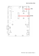
EEV-Q701 2.2 Jumper and Connector List You can configure your board to match the needs of your application by setting jumpers. A jumper is the simplest kind of electric switch. It consists of two metal pins and a small metal clip (often protected by a plastic cover) that slides over the pins to connect them. To “close” a jumper you connect the pins with the clip. To “open” a jumper you remove the clip. Sometimes a jumper will have three pins, labeled 1, 2, and 3.
Quick Installation Guide Connectors Label Function Note CN2 SDIO connector SD card slot JCPU_FAN1 CPU fan connector 4 x 1 wafer, pitch 2.54mm JBT1 Battery connector 2 x 1 wafer, pitch 2.00mm FAN1 System Fan connector 3 x 1 wafer, pitch 2.54mm JAUD1 Audio connector 6 x 2 header, pitch 2.00mm JBKL1 LCD inverter connector 5 x 1 wafer, pitch 2.0mm JCD1 CD-ROM audio connector 4 x 1 wafer, pitch 2.
EEV-Q701 2.3 Setting Jumpers & Connectors 2.3.1 Touch selector (JTOUCH1) 5W* 4/ 8W Signal PIN Y- 1 SENSE 2 NC 3 *Default 2.3.2 Brightness adjuster (JVR1) GND* .
Quick Installation Guide 2.3.3 2.3.4 Touch connector (JTOUCH2) PIN 4-WIRE 5-WIRE 8-WIRE 1 N/A N/A Right Sense 2 N/A N/A Left Sense 3 N/A N/A Bottom Sense 4 N/A Sense Top Sense 5 Right LR Right Excite 6 Left LL Left Excite 7 Bottom UR Bottom Excite 8 Top UL Top Excite 9 GND GND GND USB power selector (JUSB_PW1) Default * Signal PIN +V5A 1 USB_VCC_EN 2 +V5S 3 .
EEV-Q701 2.3.
Quick Installation Guide 2.3.
EEV-Q701 2.3.7 Module/Carrier BIOS selector (JBIOS1) Q7 Module BIOS* Carrier BIOS *Default 2.3.8 Signal PIN +3.
Quick Installation Guide 2.3.9 COM1 Dsub_ 9 signal selector (JRI1) +5V Ring* +12V * Default Signal PIN PIN Signal PS2 6 5 +12V PS2 4 3 +5V NRIA# 2 1 JNRIA# Note: When switched to “Ring”, the signal only works in RS-232 mode.
EEV-Q701 2.3.
Quick Installation Guide 2.3.11 2.3.
EEV-Q701 2.3.13 2.3.14 Battery connector (JBT1) Signal PIN GND 2 +3.
Quick Installation Guide 2.3.15 2.3.16 Audio connector (JAUD1) Signal PIN PIN Signal LINEOUT_R 1 2 LINEOUT_L GND 3 4 GND LINE1_RIN 5 6 LINE1_LIN MIC_RIN 7 8 MIC_LIN FRONT_JD 9 10 LINE1_JD MIC1_JD 11 12 GND LCD Inverter Connector (JBKL1) JBKL1 Signal PIN +5V (max.
EEV-Q701 Note: For inverters with adjustable Backlight function, it is possible to control the LCD brightness through the VR signal controlled by JVR1. Please see the JVR1 (Brightness adjuster) section for detailed circuitry information. 2.3.16.1 Signal Description – LCD Inverter Connector (JBKL1) Signal Signal Description BRIGHT Vadj = 0.75V ~ 4.25V (Recommended: 4.7KΩ, >1/16W) BLK_ON LCD backlight ON/OFF control signal 2.3.
Quick Installation Guide 2.3.18 General Purpose I/O Connector (JDIO1) Signal +5V PIN PIN 20 SMB_DATA 18 2.3.
EEV-Q701 2.3.20 PS/2 keyboard & mouse connector (JKB1) Signal 2.3.21 PIN PIN Signal KBDA 1 2 KBCK GND_PS2 3 4 VCC_PS2 MSDA 5 6 MSCK NC 7 LPC Connector (JLPC1) 24 EEV-Q701 Quick Installation Guide Signal PIN PIN Signal LPC_AD0 1 2 +3.
Quick Installation Guide 2.3.22 LVDS connector (JLVDS1) Signal PIN PIN Signal +3.3V 1 2 +5V +3.
EEV-Q701 2.3.23 SPI connector (JSPI1) Signal PIN PIN Signal 2.3.24 +3.
Quick Installation Guide 2.3.
EEV-Q701 Signal PIN PIN Signal Signal PIN PIN Signal LVDS_A1- 105 106 LVDS_B1- LVDS_A2+ 107 108 LVDS_B2+ PCIE1_TX+ 173 174 PCIE1_RX+ LVDS_A2- 109 110 LVDS_B2- PCIE1_TX- 175 176 PCIE1_RX- LVDS_PPEN 111 112 LVDS_BLEN EXCD0_CPPE# 177 178 EXCD1_CPPE# LVDS_A3+ 113 114 LVDS_B3+ PCIE0_TX+ 179 180 PCIE0_RX+ LVDS_A3- 115 116 LVDS_B3 PCIE0_TX- 181 182 PCIE0_RX- GND15 117 118 GND16 GND27 183 184 GND28 LVDS_A_CLK+ 119 120 LVDS_B_CLK+ LPC_AD0 185 186 LPC_AD1 LVDS_A_CLK