EMS-BYT Series Fanless Intel® Celeron®/Atom™ SoC Rugged Embedded System Quick Reference Guide 2nd Ed –29 September 2014 Copyright Notice Copyright 2014 Avalue Technology Inc., ALL RIGHTS RESERVED. Part No.
EMS-BYT Series FCC Statement THIS DEVICE COMPLIES WITH PART 15 FCC RULES. OPERATION IS SUBJECT TO THE FOLLOWING TWO CONDITIONS: (1) THIS DEVICE MAY NOT CAUSE HARMFUL INTERFERENCE. (2) THIS DEVICE MUST ACCEPT ANY INTERFERENCE RECEIVED INCLUDING INTERFERENCE THAT MAY CAUSE UNDESIRED OPERATION. THIS EQUIPMENT HAS BEEN TESTED AND FOUND TO COMPLY WITH THE LIMITS FOR A CLASS "A" DIGITAL DEVICE, PURSUANT TO PART 15 OF THE FCC RULES.
Quick Reference Guide Content 1. Getting Started ............................................................................................................ 7 1.1 1.2 1.3 1.4 2. Safety Precautions ................................................................................................ 7 Packing List ........................................................................................................... 7 System Specifications ..................................................................
EMS-BYT Series 2.4.9 LCD inverter connector (JBKL1) ................................................................................................ 30 2.4.10 SPI connector (SPI1) ............................................................................................................. 30 2.4.11 Front Panel Connector 1 (CN1) ............................................................................................. 31 2.4.12 Front Panel Connector 2 (CN2) .........................................
Quick Reference Guide 3.6.1.1 System Language ............................................................................................................. 51 3.6.1.2 System Date ...................................................................................................................... 51 3.6.1.3 System Time ..................................................................................................................... 51 3.6.2 Advanced Menu ...........................................
EMS-BYT Series 4. Drivers Installation....................................................................................................... 79 4.1 4.2 4.3 4.4 4.5 4.6 6 Install Chipset Driver ........................................................................................... 80 Install MBI Driver ................................................................................................. 81 Install TXE Driver ..................................................................................
Quick Reference Guide 1. Getting Started 1.1 Safety Precautions Warning! Always completely disconnect the power cord from your chassis whenever you work with the hardware. Do not make connections while the power is on. Sensitive electronic components can be damaged by sudden power surges. Only experienced electronics personnel should open the PC chassis. Caution! Always ground yourself to remove any static charge before touching the CPU card.
EMS-BYT Series 1.
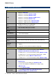
Quick Reference Guide 1 x VGA, 1 x HDMI (EMS-BYT-HDMI) 1 x VGA, 1 x DVI (EMS-BYT-DVI) Audio Port Mic-in, Line-in, Line-out GPIO 6-bit GPI and 6-bit GPO 3 x USB 2.0 (Rear 2; Front 1) (EMS-BYT) 5 x USB 2.
EMS-BYT Series 1hr/axis Protection Shock Protection With mSATA/SSD: 50G, IEC 60068-2-27, Half Sine, 11ms CE, FCC Class B (EMS-BYT, EMS-BYT-6COM, EMS-BYT-5LAN, Certification Dimension (W x H x EMS-BYT-4COM Isolation, EMS-BYT-HDMI, EMS-BYT-DVI) CE, FCC Class A (EMS-BYT-PoE) 240mm x 170mm x 45mm (EMS-BYT) 240mm x 170mm x 60mm (EMS-BYT-6COM, EMS-BYT-5LAN, D) EMS-BYT-4COM Isolation, EMS-BYT-PoE, EMS-BYT-HDMI, EMS-BYT-DVI) Weight 10 4.
Quick Reference Guide 1.4 System Overview 1.4.
EMS-BYT Series 1.4.2 Front View 1.4.
Quick Reference Guide EMS-BYT-5LAN/PoE EMS-BYT-HDMI EMS-BYT-DVI EMS-BYT Series Quick Reference Guide 13
EMS-BYT Series EMS-BYT Connectors Label Function COM1 Serial port connector 1 DC-IN DC power-in connector LAN1 RJ-45 Ethernet 1 Multi-function port Note Multi-Function Port combined COM2, 2 PS/2, Audio, GPIO and SMBus USB1~3 USB connector 1~3 VGA VGA connector Swappable Drawer 2.
Quick Reference Guide Swappable Drawer 2.5” Driver Bay and SIM Card HDD HDD indicator EMS-BYT-HDMI Connectors Label Function COM1 Serial port connector 1 COM3~4 Serial port connector 3~4 DC-IN DC power-in connector LAN1~3 RJ-45 Ethernet 1~3 Multi-function port Note Multi-Function Port combined COM2, 2 PS/2, Audio, GPIO and SMBus USB1~5 USB connector 1~5 VGA VGA connector Swappable Drawer 2.
EMS-BYT Series 2. Hardware Configuration Jumper and Connector Setting, Driver and BIOS Installing For advanced information, please refer to: 1- EBM-BYTS, AUX-M01, AUX-M02, AUX-M04, AUX-M07, EBM-BYTS DB-A and EBM-CDVS DB-A included in this manual. Note: If you need more information, please visit our website: http://www.avalue.com.
Quick Reference Guide 2.1 EMS-BYT connector mapping 2.1.1 2.1.
EMS-BYT Series 2.1.3 VGA connector (VGA) PIN Signal PIN Signal PIN Signal 1 RED 6 GND 11 NC 2 GREEN 7 GND 12 DDCDAT 3 BLUE 8 GND 13 HSYNC 4 NC 9 +5V 14 VSYNS 5 GND 10 GND 15 DDCCLK 2.1.
Quick Reference Guide 2.1.4.1 GPIO+SMBUS Signal PIN PIN 25 13 24 12 23 11 22 10 SMBUS_DATA 21 9 SMBUS_CLK 20 8 GPI-D5 19 7 GPI-D4 18 6 GPI-D3 17 5 GPI-D2 16 4 GPI-D1 15 3 GPI-D0 14 2 1 Signal GND 5V GPO-D5 GPO-D4 GPO-D3 GPO-D2 GPO-D1 GPO-D0 2.1.4.
EMS-BYT Series 2.2 EBM-BYTS, AUX-M01, AUX-M02, AUX-M04, AUX-M07, EBM-BYTS DB-A and EBM-CDVS DB-A Overviews 2.2.
Quick Reference Guide 2.2.2 AUX-M01 2.2.
EMS-BYT Series 2.2.4 AUX-M04 2.2.
Quick Reference Guide 2.2.6 EBM-BYTS DB-A 2.2.
EMS-BYT Series 2.3 EBM-BYTS Jumper & Connector list Jumpers Label Function Note JCMOS1 Clear CMOS 3 x 1 header, pitch 2.54mm JCMOS2 Clear CMOS (Reserved) 3 x 1 header, pitch 2.54 mm JRI1/2 COM 1/2 pin 9 signal select 3 x 2 header, pitch 2.00 mm JAT1 AT/ ATX Input power select 3 x 1 header, pitch 2.00 mm SW1 Serial port 1/ 2 – RS485 mode select DIP switch 6pin JUIM1 UIM Switch select JVR1 LCD backlight brightness adjustment 3 x 1 header, pitch 2.
Quick Reference Guide SO_DIMM1 DDR3 SODIMM connector MIOE_CB1 IET Expansion slot JLPC1 LPC port connector 7 x 2 header, pitch 2.00 mm SPI1 SPI connector 4 x 2 header, pitch 2.00 mm JBKL1 LCD inverter connector 5 x 1 wafer, pitch 2.00 mm SATA1 Serial ATA connector 1 CN1 Front Panel connector 1 5 x 1 wafer, pitch 2.00 mm CN2 Front Panel connector 2 8 x 1 wafer, pitch 2.00 mm DCOUT_S1 DC Output connector 6 x 1 wafer, pitch 2.00 mm JEC_ROM1 EC Debug connector 5 x 2 header, pitch 2.
EMS-BYT Series 2.4 EBM-BYTS Jumpers & Connectors settings 2.4.1 Clear CMOS (JCMOS1) Protect* Clear CMOS *Default 2.4.
Quick Reference Guide 2.4.3 AT/ ATX Input power select (JAT1) AT* ATX *Default 2.4.
EMS-BYT Series 2.4.5 IET interface DP mode select (JDDI1) HDMI/DVI Display Port* *Default 2.4.
Quick Reference Guide 2.4.7 Serial port 1/ 2 – RS485 mode select (SW1) In Serial Port 1 mode 1 2 3 ON OFF Auto Direction RTS# Control* 485TXP external OPEN* biasing resistor 485TXN external OPEN* biasing resistor In Serial Port 2 mode 4 5 6 2.4.8 ON OFF Auto Direction RTS# Control* 485TXP external OPEN* biasing resistor 485TXN external OPEN* biasing resistor LPC port connector (JLPC1) Signal PIN PIN Signal LPC_AD0 1 2 +3.
EMS-BYT Series 2.4.9 2.4.
Quick Reference Guide 2.4.11 2.4.12 Front Panel Connector 1 (CN1) Signal PIN PWR_BTN_IN# 1 SYSRST# 2 GND 3 +5VSB 4 PWR_LED- 5 Front Panel Connector 2 (CN2) Signal PIN +3.3V 1 SATA_5V_LED# 2 +3.3VSB 3 LAN1_LED_ACT_n 4 +3.3VSB 5 LAN1_LED_100#_n 6 +3.
EMS-BYT Series 2.4.13 2.4.
Quick Reference Guide 2.4.15 2.4.16 On-board header for USB2.0 (JUSB1) Signal PIN USBVCC_HEADER 1 USB_HUB2_DN_1 2 USB_HUB2_DP_1 3 GND 4 GND 5 LVDS connector (JLVDS1) Signal PIN PIN Signal +5V 2 1 +3.3V +5V 4 3 +3.
EMS-BYT Series 2.5 AUX-M01, AUX-M02, AUX-M04, AUX-M07, EBM-BYTS DB-A and EBM-CDVS DB-A Jumper & Connector list 2.5.1 AUX-M01 Jumpers Label Function Note JRI3/4/5/6 COM 3/4/5/6 pin 9 signal select 3 x 2 header, pitch 2.00mm Label Function Note USB1~2 USB connector 1~2 USB3 USB connector 3 5 x 1 wafer, pitch 2.00mm JUSB3 USB connector 3 5 x 1 header, pitch 2.00mm COM3~6 Serial port connector 3~6 PJP1 SMBUS of TCA9555 address setting Connectors 2.5.2 3 x 2 header, pitch 2.
Quick Reference Guide 2.5.4 AUX-M07 Connectors Label Function USB1~2 USB connector 1~2 COM3~6 Serial port connector 3~6 SJP2 SMBUS of TCA9555 address setting 2.5.5 Note 3 x 2 header, pitch 2.00mm EBM-BYTS DB-A Jumpers Label Function Note OJRI3/4 COM 3/4 pin 9 signal select 3 x 2 header, pitch 2.00mm Label Function Note OUSB1~2 USB connector 1~2 LAN2~3 LAN connector 2~3 COM3~4 Serial port connector 3~4 HDMI1 HDMI connector 3 x 2 header, pitch 2.
EMS-BYT Series 2.6 AUX-M01 Jumpers & Connectors settings 2.6.1 COM 3/4/5/6 pin 9 signal select (JRI3/4/5/6) +5V JRI6 Ring* JRI5 +12V JRI4 JRI3 * Default 2.6.
Quick Reference Guide 2.6.3 2.6.
EMS-BYT Series 2.7 AUX-M02 Connectors settings 2.7.1 LAN ACT/LNK/SPD LED (JLANLED) Signal 2.7.2 Signal Z_LAN_LED_1000#_3 15 16 Z_LAN_LED_1000#_1 Z_LAN_LED_100#_3 13 14 Z_LAN_LED_100#_1 Z_LAN_LED_ACT_3 11 12 Z_LAN_LED_ACT_1 +3.3VSB 9 10 +3.3VSB Z_LAN_LED_1000#_4 7 8 Z_LAN_LED_1000#_2 Z_LAN_LED_100#_4 5 6 Z_LAN_LED_100#_2 Z_LAN_LED_ACT_4 3 4 Z_LAN_LED_ACT_2 +3.3VSB 1 2 +3.
Quick Reference Guide 2.8 AUX-M04 Jumpers & Connectors settings 2.8.1 Operating Modes select (ZJP1) Normal Auto* Reset * Default 2.8.
EMS-BYT Series 2.8.3 LAN ACT/LNK/SPD LED (Z_JLANLED) Signal 40 PIN PIN Signal Z_LAN_LED_1000#_3 15 16 Z_LAN_LED_1000#_1 Z_LAN_LED_100#_3 13 14 Z_LAN_LED_100#_1 Z_LAN_LED_ACT_3 11 12 Z_LAN_LED_ACT_1 +3.3VSB 9 10 +3.3VSB Z_LAN_LED_1000#_4 7 8 Z_LAN_LED_1000#_2 Z_LAN_LED_100#_4 5 6 Z_LAN_LED_100#_2 Z_LAN_LED_ACT_4 3 4 Z_LAN_LED_ACT_2 +3.3VSB 1 2 +3.
Quick Reference Guide 2.9 AUX-M07 Connector settings 2.9.
EMS-BYT Series 2.10 EBM-BYTS DB-A Jumpers & Connectors settings 2.10.1 COM 3/4 pin 9 signal select (OJRI3/4) +5V Ring* OJRI4 +12V OJRI3 * Default 2.10.
Quick Reference Guide 2.10.
EMS-BYT Series 2.11 EBM-CDVS DB-A Connector settings 2.11.
Quick Reference Guide 2.12 Installing Hard Disk & Memory, PCI devices (EMS-BYT Series) Step 1. Remove 6 screws from the bottom of your system. Step 2. Remove the chassis cover. Step 1. Remove 5 screws to release the HDD bracket. Step 2.1 Slide HDD into its bracket until properly seated. Step 2.2 Secure HDD by means of 5 screws. Step 3. Slide the DDR3 SODIMM into the memory socket and press it down until properly seated. Step 4.
EMS-BYT Series 2.13 Installing Mounting Brackets (EMS-BYT Series) Step 1. Position brackets on both sides, matching the holes on the system. Step 2. Insert and fasten screw on each side of the system to secure Mounting brackets.
Quick Reference Guide 3.
EMS-BYT Series 3.1 Introduction The BIOS setup program allows users to modify the basic system configuration. In this following chapter will describe how to access the BIOS setup program and the configuration options that may be changed. 3.2 Starting Setup The AMI BIOS™ is immediately activated when you first power on the computer. The BIOS reads the system information contained in the NVRAM and begins the process of checking out the system and configuring it.
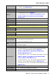
Quick Reference Guide 3.3 Using Setup In general, you use the arrow keys to highlight items, press to select, use the PageUp and PageDown keys to change entries, press for help and press to quit. The following table provides more detail about how to navigate in the Setup program using the keyboard.
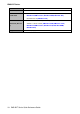
EMS-BYT Series 3.4 Getting Help Press F1 to pop up a small help window that describes the appropriate keys to use and the possible selections for the highlighted item. To exit the Help Window press or the F1 key again. 3.5 In Case of Problems If, after making and saving system changes with Setup, you discover that your computer no longer is able to boot, the AMI BIOS supports an override to the NVRAM settings which resets your system to its defaults.
Quick Reference Guide 3.6 BIOS setup Once you enter the Aptio Setup Utility, the Main Menu will appear on the screen. The Main Menu allows you to select from several setup functions and exit choices. Use the arrow keys to select among the items and press to accept and enter the sub-menu. 3.6.1 Main Menu This section allows you to record some basic hardware configurations in your computer and set the system clock. 3.6.1.1 System Language This option allows choosing the system default language. 3.6.
EMS-BYT Series 3.6.2 Advanced Menu This section allows you to configure your CPU and other system devices for basic operation through the following sub-menus. 3.6.2.1 ACPI Settings 52 Item Enable ACPI Auto Configuration Options Disabled[Default], Enabled Enable Hibernation Disabled Enabled[Default], EMS-BYT Series Quick Reference Guide Description Enables or Disables BIOS ACPI Auto Configuration. Enables or Disables System ability to Hibernate (OS/S4 Sleep State).
Quick Reference Guide ACPI Sleep State Suspend Disabled, S3 (Suspend to RAM) [Default] ErP Function Disabled[Default], Enabled PWR-On After PWR-Fail Watch Dog Off[Default] On Last state Disabled[Default], 30 sec 40 sec 50 sec 1 min 2 min 10 min 30 min OS. Select the highest ACPI sleep state the system will enter when the SUSPEND button is pressed. ErP Function (Deep S5). AC loss resume. Select WatchDog. 3.6.2.
EMS-BYT Series Serial Port 5 Configuration Set Parameters of Serial Port 5 (COME). Serial Port 6 Configuration Set Parameters of Serial Port 6 (COMF). 3.6.2.2.
Quick Reference Guide 3.6.2.2.2 Serial Port 2 Configuration Item Serial Port Change Settings UART 232 422 485 422/ 485 termination Slew limiting Option Enabled[Default], Disabled Auto[Default] IO=2F8h; IRQ=3; IO=3F8h; IRQ=3,4,5,6,7,9,10,11,12; IO=2F8h; IRQ=3,4,5,6,7,9,10,11,12; IO=3E8h; IRQ=3,4,5,6,7,9,10,11,12; IO=2E8h; IRQ=3,4,5,6,7,9,10,11,12; UART 232 (LOOPBACK) UART 232[Default] UART 485 UART 422 Disabled[Default] Enabled 10M bps 250k bps[Default] Description Enable or Disable Serial Port (COM).
EMS-BYT Series 3.6.2.2.
Quick Reference Guide 3.6.2.2.4 Serial Port 4 Configuration Item Serial Port Change Settings UART 232 422 485 422/ 485 termination Slew limiting Option Enabled[Default], Disabled Auto[Default] IO=2E8h; IRQ=10; IO=3F8h; IRQ=3,4,5,6,7,10,11,12; IO=2F8h; IRQ=3,4,5,6,7,10,11,12; IO=3E8h; IRQ=3,4,5,6,7,10,11,12; IO=2E8h; IRQ=3,4,5,6,7,10,11,12; UART 232 (LOOPBACK) UART 232[Default] UART 485 UART 422 Disabled[Default] Enabled 10M bps 250k bps[Default] Description Enable or Disable Serial Port (COM).
EMS-BYT Series 3.6.2.2.
Quick Reference Guide 3.6.2.2.6 Serial Port 6 Configuration Item Serial Port Change Settings UART 232 422 485 422/ 485 termination Slew limiting Option Enabled[Default], Disabled Auto[Default] IO=208h; IRQ=10; IO=200h; IRQ=3,4,5,6,7,10,11,12; IO=208h; IRQ=3,4,5,6,7,10,11,12; IO=210h; IRQ=3,4,5,6,7,10,11,12; IO=218h; IRQ=3,4,5,6,7,10,11,12; UART 232 (LOOPBACK) UART 232[Default] UART 485 UART 422 Disabled[Default] Enabled 10M bps 250k bps[Default] Description Enable or Disable Serial Port (COM).
EMS-BYT Series 3.6.2.3 EC 8528 H/W Monitor 3.6.2.4 S5 RTC Wake Settings 60 Item Options Wake system from S5 Disabled[Default], Fixed Time Dynamic Time EMS-BYT Series Quick Reference Guide Description Enable or disable System wake on alarm event. Select Fixed Time, system will wake on the hr::min::sec specified. Select Dynamic Time, System will wake on the current time + Increase minute(s).
Quick Reference Guide 3.6.2.5 Serial Port Console Redirection Item Console Redirection Options Disabled[Default], Enabled Description Console Redirection Enable or Disable. 3.6.2.6 CPU Configuration Use the CPU configuration menu to view detailed CPU specification and configure the CPU. Item Active Processor Cores Options All[Default], 1 Description Number of cores to enable in each processor package.
EMS-BYT Series Limit CPUID Maximum Disabled[Default], Enabled Execute Disable Bit Disabled, Enabled[Default] Intel Virtualization Technology Disabled, Enabled[Default] Power Technology Disabled, Energy Efficient[Default] Custom 3.6.2.6.1 Socket 0 CPU Information 62 EMS-BYT Series Quick Reference Guide Disabled for Windows XP. XD can prevent certain classes of malicious buffer overflow attacks when combined with a supporting OS (Windows Server 2003 SP1, Windows XP SP2, SuSE Linux 9.
Quick Reference Guide 3.6.2.7 PPM Configuration Item Options CPU C state Report Disabled, Enabled[Default] Max CPU C-state C7[Default] C6 C1 Description Enable/Disable CPU C state report to OS. This option controls Max C state that the processor will support. 3.6.2.
EMS-BYT Series Item Serial-ATA (SATA) SATA Speed Support SATA ODD Port Options Enabled[Default] Disabled, Gen1 Gen2[Default] Port0 ODD Port1 ODD No ODD[Default] SATA Mode IDE Mode AHCI Mode[Default] Serial-ATA Port 0/1 Enabled[Default] Disabled, Description Enable/Disable Serial ATA. SATA Speed Support Gen1 or Gen2. SATA ODD is Port0 or Port1. Select IDE/ AHCI. Enable/Disable Serial ATA Port0/1. 3.6.2.
Quick Reference Guide Boot option filter Network Storage Video Other PCI devices UEFI and Legacy Legacy only[Default] UEFI only Do not launch[Default] UEFI only Legacy only Do not launch UEFI only Legacy only[Default] Do not launch UEFI only Legacy only[Default] UEFI only Legacy only[Default], This option controls Legacy/UEFI ROMs priority. Controls the execution of UEFI and Legacy PXE OpROM. Controls the execution of UEFI and Legacy Storage OpROM.
EMS-BYT Series Boot option filter Network Storage Video Other PCI devices UEFI and Legacy Legacy only[Default] UEFI only Do not launch[Default] UEFI only Legacy only Do not launch UEFI only Legacy only[Default] Do not launch UEFI only Legacy only[Default] UEFI only Legacy only[Default], This option controls Legacy/UEFI ROMs priority. Controls the execution of UEFI and Legacy PXE OpROM. Controls the execution of UEFI and Legacy Storage OpROM. Controls the execution of UEFI and Legacy Video OpROM.
Quick Reference Guide 1 sec 5 sec 10 sec 20 sec[Default] 10 sec 20 sec[Default] 30 sec 40 sec USB transfer time-out Device reset time-out Auto[Default] Manual Device power-up delay The time-out value for Control, Bulk, and Interrupt transfers. USB mass storage device Start Unit command time-out. Maximum time the device will take before it properly reports itself to the Host Controller. ‘Auto’ uses default value: for a Root port it is 100ms, for a Hub port the delay is taken form Hub descriptor. 3.6.
EMS-BYT Series 3.6.3 Chipset 3.6.3.
Quick Reference Guide 3.6.3.1.
EMS-BYT Series 3.6.3.1.
Quick Reference Guide 1680x1050 24/2 LVDS Back Light PWM 3.6.3.2 00% 25% 50% 75% 100%[Default] Select LVDS back light PWM duty. South Bridge Item High Precision Timer Option Disabled Enabled[Default] Description Enable or Disable the High Precision Event Timer.
EMS-BYT Series 3.6.3.2.1 Azalia HD Audio Item Option Audio Controller Enabled[Default], Disabled HDMI Port B Enabled[Default], Disabled 3.6.3.2.2 USB Configuration 72 EMS-BYT Series Quick Reference Guide Description Control Detection of the Azalia device. Disabled = Azalia will be unconditionally disabled. Enabled = Azalia will be unconditionally Enabled. Auto = Azalia will be enabled if present disabled otherwise. Enable/Disable HDMI Port B.
Quick Reference Guide Item Option OS Selection Windows 8.X[Default] Android Windows 7 XHCI Mode Enabled[Default], Disabled Auto Smart Auto Description Please select the corresponding type of Windows for OS installation. Please change the item of OS selection to Windows 7 if you intend to install Windows 7 OS; Please change the item of OS selection to Windows 8.X if you intend to install Windows 8 OS. Mode of operation of xHCI controller. 3.6.3.2.
EMS-BYT Series 3.6.4 Security Administrator Password Set setup Administrator Password User Password Set User Password 3.6.4.
Quick Reference Guide Item Option Secure Boot Disabled[Default] Enabled Secure Boot Mode Standard Custom[Default] Description Secure Boot can be enabled if 1.System running in User mode with enrolled Platform Key(PK) 2.CSM function is disabled. Secure Boot mode selector. ‘Custom’ Mode enables users to change Image Execution policy and manage Secure Boot Keys. 3.6.4.1.
EMS-BYT Series 3.6.5 Boot Item Option Setup Prompt Timeout 1~ 65535 Bootup NumLock State Quiet Boot Fast Boot Boot Option #1/2 76 On[Default] Off Disabled[Default] Enabled Disabled[Default] Enabled Description Number of seconds to wait for setup activation key. 65535(0xFFFF) means indefinite waiting. Select the Keyboard NumLock state Enables or disables Quiet Boot option Enables or disables boot with initialization of a minimal set of devices required to launch active boot option.
Quick Reference Guide 3.6.6 Save and exit 3.6.6.1 Save Changes and Reset Reset the system after saving the changes. 3.6.6.
EMS-BYT Series discarded. The setup program then exits and reboots the controller. 3.6.6.3 Restore Defaults This option restores all BIOS settings to the factory default. This option is useful if the controller exhibits unpredictable behavior due to an incorrect or inappropriate BIOS setting. 3.6.6.4 Launch EFI Shell from filesystem device Attempts to Launch EFI Shell application (Shellx64.efi) from one of the available filesystem devices.
Quick Reference Guide 4. Drivers Installation Note: Installation procedures and screen shots in this section are for your reference and may not be exactly the same as shown on your screen.
EMS-BYT Series 4.1 Install Chipset Driver Insert the Supporting DVD-ROM to DVD-ROM drive, and it should show the index page of Avalue’s products automatically. If not, locate Index.htm and choose the product from the menu left, or link to \Driver_Chipset\Intel\EMS-BYT. Note: The installation procedures and screen shots in this section are based on Windows 8.1 operation system. If the warning message appears while the installation process, click Continue to go on. Step 3. Click Install. Step 4.
Quick Reference Guide 4.2 Install MBI Driver Insert the Supporting DVD-ROM to DVD-ROM drive, and it should show the index page of Avalue’s products automatically. If not, locate Index.htm and choose the product from the menu left, or link to \Utility\EMS-BYT_MBI. Note: The installation procedures and screen shots in this section are based on Windows 8.1 operation system. If the warning message appears while the installation process, click Continue to go on. Step 3. Click Next to proceed setup. Step 4.
EMS-BYT Series 4.3 Install TXE Driver Insert the Supporting DVD-ROM to DVD-ROM drive, and it should show the index page of Avalue’s products automatically. If not, locate Index.htm and choose the product from the menu left, or link to \Utility\EMS-BYT_TXE. Note: The installation procedures and screen shots in this section are based on Windows 8.1 operation system. If the warning message appears while the installation process, click Continue to go on. Step1. Click Next to start installation. Step 2.
Quick Reference Guide 4.4 Install VGA Driver Insert the Supporting DVD-ROM to DVD-ROM drive, and it should show the index page of Avalue’s products automatically. If not, locate Index.htm and choose the product from the menu left, or link to \VGA\EMS-BYT. Note: The installation procedures and screen shots in this section are based on Windows 8.1 operation system. Step 3. Click Next. Step 1. Click Next to continue installation. Step 2. Click Yes to accept license agreement. Step 4. Click Next. Step 5.
EMS-BYT Series 4.5 Install Audio Driver (For Realtek ALC892) Insert the Supporting CD-ROM to CD-ROM drive, and it should show the index page of Avalue’s products automatically. If not, locate Index.htm and choose the product from the menu left, or link to \Driver_Audio\Realtek\ALC892\EMS-BYT_Audio. Note: The installation procedures and screen shots in this section are based on Windows 8.1 operation system. Step 1. Click Next to continue setup. Step 2. Click Finish to complete the setup.
Quick Reference Guide 4.6 Install Ethernet Driver Insert the Supporting DVD-ROM to DVD-ROM drive, and it should show the index page of Avalue’s products automatically. If not, locate Index.htm and choose the product from the menu left, or link to \Driver_Gigabit\Intel\I210\EMS-BYT_LAN. Note: The installation procedures and screen shots in this section are based on Windows 8.1 operation system. Step 3. Click Next. Step 4. Click Install to proceed. Step 1. Click Next. Step 2.