EMS-CDV Fanless Intel® Atom™ D2550 Rugged Embedded System with Intel® NM10 Express Chipset Quick Reference Guide 3rd Ed –25 July 2013 Copyright Notice Copyright 2013 Avalue Technology Inc., ALL RIGHTS RESERVED. Part No.
EMS-CDV 1. Getting Started 1.1 Safety Precautions Warning! Always completely disconnect the power cord from your chassis whenever you work with the hardware. Do not make connections while the power is on. Sensitive electronic components can be damaged by sudden power surges. Only experienced electronics personnel should open the PC chassis. Caution! Always ground yourself to remove any static charge before touching the CPU card. Modern electronic devices are very sensitive to static electric charges.
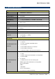
Quick Reference Guide 1.3 System Specifications System CPU Intel® D2550 1.86GHz CPU BIOS AMI uEFI BIOS, 16Mbit SPI Flash ROM System Chipset Intel NM10 I/O Chip Nuvoton W83627DHG-P System Memory 1 x 204-pin SODIMM Up to 4GB DDR3 1066 SDRAM Front Access Swappable 2.5” Drive Bay and mSATA on 1st Mini Stroage PCIe Socket Watchdog Timer Reset: 1sec. ~ 65535sec./min. and 1sec. or 1min.
EMS-CDV Chipset IDT IDT89HPES5T5ZBBCG PCIe switch Interface 5-Port/5-lane(for MI/Oe) Chipset Cedarview integrated Resolution VGA: 1920x1200 Chipset 1 x Intel 82574L GbE controller Ethernet Interface 10/100/1000 Base-Tx GbE compatible Chipset Realtek ALC892 HD codec Audio Interface Mic-In, Line-Inand Line-Out Display Ethernet Audio Mechanical & Environmental +12 ~ +26Vdc Single Power ATX Support S0, S3, S4, S5 ACPI 3.
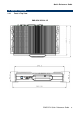
Quick Reference Guide 1.4 System Overview 1.4.
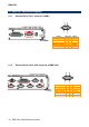
EMS-CDV EMS-CDV-255-A1-2R/3R 1.4.
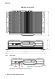
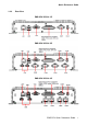
Quick Reference Guide 1.4.
EMS-CDV EMS-CDV-255-A1-1R Connectors Label Function COM1 Serial port connector 1 DC-IN DC power-in connector LAN1 RJ-45 Ethernet 1 Multi-function port Note Multi-Function Port combined COM2, 2 PS/2, Audio, GPIO and SMBus USB1~3 USB connector 1~3 VGA VGA connector Swappable Drawer 2.
Quick Reference Guide 2. Hardware Configuration Jumper and Connector Setting, Driver and BIOS Installing For advanced information, please refer to: 1- EBM-CDVS, AUX-M01 and AUX-M02 included in this manual. Note: If you need more information, please visit our website: http://www.avalue.com.
EMS-CDV 2.1 EMS-CDV connector mapping 2.1.1 External Serial Port 1 connector (COM1) Signal PIN PIN Signal NDCDA#_485TXN 1 6 NDSRA# NRXDA#_485TXP 2 7 NRTSA# NTXDA#_485RXP 3 8 NCTSA# NDTRA#_485RXN 4 9 NRIA# GND 5 - 2.1.
Quick Reference Guide 2.1.3 VGA connector (VGA) PIN Signal PIN Signal PIN Signal 1 RED 6 GND 11 NC 2 GREEN 7 GND 12 SDT_DDC 3 BLUE 8 GND 13 VGA_HS 4 NC 9 +5V 14 VGA_VS 5 GND 10 GND 15 SCK_DDC 2.1.
EMS-CDV 2.1.4.1 GPIO+SMBUS Signal PIN PIN 25 13 24 12 23 11 22 10 SMBUS_DATA 21 9 SMBUS_CLK 20 8 GPI-D5 19 7 GPI-D4 18 6 GPI-D3 17 5 GPI-D2 16 4 GPI-D1 15 3 GPI-D0 14 2 1 Signal GND 5V GPO-D5 GPO-D4 GPO-D3 GPO-D2 GPO-D1 GPO-D0 2.1.4.
Quick Reference Guide 2.2 EBM-CDVS,AUX-M01 and AUX-M02 Overviews 2.2.
EMS-CDV 14 EMS-CDV Quick Reference Guide
Quick Reference Guide 2.2.2 AUX-M01 2.2.
EMS-CDV 2.3 EBM-CDVS Jumper & Connector list Jumpers Label CMOS1 JRI1/2 Function Clear CMOS COM 1/2 pin 9 signal select Note 3 x 1 header, pitch 2.54mm 3 x 2 header, pitch 2.00mm Connectors Label USB_REAR USB_FRONT LAN1 CRT1 Function USB connector USB connector LAN connector VGA connector Note 1. COM2 2. Audio(line-in, line-out, mic-in) 3. 2 x PS/2 for KB/MS, 4.
Quick Reference Guide 2.4 EBM-CDVS Jumpers & Connectors settings 2.4.1 Clear CMOS (CMOS1) Protect* Clear CMOS *Default 2.4.
EMS-CDV 2.4.3 2.4.
Quick Reference Guide 2.4.5 2.4.6 LCD inverter connector (BKL1) Signal PIN +12V 1 GND 2 LVDS_BKLTEN 3 BRIGHT 4 +5V 5 LCD backlight brightness adjustment (JVR) Signal PIN +5V 1 BRIGHT 2 GND 3 Variation Resistor (Recommended: 4.
EMS-CDV 2.4.7 2.4.
Quick Reference Guide 2.4.9 2.4.
EMS-CDV 2.4.11 AT/ATX mode selector (SW1) AT/ATX mode s AT mode ATX mode* *Default 2.4.11.1 Signal Description –AT/ATX mode selection AT/ATX mode Description AT mode This Mode supports AT power supply, no need to press Power button to enable power on/off ATX mode This Mode supports ATX power supply.
Quick Reference Guide 2.5 AUX-M01,AUX-M02 Jumper & Connector list 2.5.1 AUX-M01 Jumpers Label Function Note JRI3/4/5/6 COM 3/4/5/6 pin 9 signal select 3 x 2 header, pitch 2.00mm Label Function Note USB1~2 USB connector 1~2 USB3 USB connector 3 5 x 1 wafer, pitch 2.00mm JUSB3 USB connector 3 5 x 1 header, pitch 2.00mm COM3~6 Serial port connector 3~6 Connectors 2.5.
EMS-CDV 2.6 AUX-M01 Jumpers & Connectors settings 2.6.1 COM 3/4/5/6 pin 9 signal select (JRI3/4/5/6) +5V JRI6 Ring* JRI5 +12V JRI4 JRI3 * Default 2.6.
Quick Reference Guide 2.6.
EMS-CDV 2.7 AUX-M02 Jumpers & Connectors settings 2.7.1 2.7.
Quick Reference Guide 2.8 Installing Hard Disk & Memory, PCI devices (EMS-CDV) Step 1. Remove 6 screws from the bottom of your system. Step 2. Remove the chassis cover. Step 1. Remove 5 screws to release the HDD bracket. Step 2.1. Slide HDD into its bracket until properly seated. Step 2.2. Secure HDD by means of 5 screws. Step 3. Slide the DDR3 SODIMM into the memory socket and press it down until properly seated. Step 4.
EMS-CDV 2.9 Installing Mounting Brackets (EMS-CDV) Step 1. Position brackets on both sides, matching the holes on the system. Step 2. Insert and fasten screw on each side of the system to secure Mounting brackets.