EMX-CDD Intel® Atom™ D2550 Process + NM10 Chipset Mini ITX Motherboard Quick Installation Guide 1st Ed – 23 August 2013 Part No.
EMX-CDD Quick Installation Guide FCC Statement THIS DEVICE COMPLIES WITH PART 15 FCC RULES. OPERATION IS SUBJECT TO THE FOLLOWING TWO CONDITIONS: (1) THIS DEVICE MAY NOT CAUSE HARMFUL INTERFERENCE. (2) THIS DEVICE MUST ACCEPT ANY INTERFERENCE RECEIVED INCLUDING INTERFERENCE THAT MAY CAUSE UNDESIRED OPERATION. THIS EQUIPMENT HAS BEEN TESTED AND FOUND TO COMPLY WITH THE LIMITS FOR A CLASS "A" DIGITAL DEVICE, PURSUANT TO PART 15 OF THE FCC RULES.
EMX-CDD Quick Installation Guide 1. Getting Started 1.1 Safety Precautions Warning! Always completely disconnect the power cord from your chassis whenever you work with the hardware. Do not make connections while the power is on. Sensitive electronic components can be damaged by sudden power surges. Only experienced electronics personnel should open the PC chassis. Caution! Always ground yourself to remove any static charge before touching the CPU card.
EMX-CDD Quick Installation Guide 2.
EMX-CDD Quick Installation Guide 2.
EMX-CDD Quick Installation Guide 2.2 Jumper and Connector List You can configure your board to match the needs of your application by setting jumpers. A jumper is the simplest kind of electric switch. It consists of two metal pins and a small metal clip (often protected by a plastic cover) that slides over the pins to connect them. To “close” a jumper you connect the pins with the clip. To “open” a jumper you remove the clip. Sometimes a jumper will have three pins, labeled 1, 2, and 3.
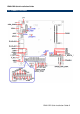
EMX-CDD Quick Installation Guide Connectors Label Function Note FPANEL1 Front Panel Switches 2 x 8 header, pitch 2.54 mm MPCIE_WIFI_SATA PCIE signal selector HDMI1 HDMI connector J1 ATX power connector for DC 12V input JSPK Speaker connector 1 x 4 wafer, pitch 2.00 mm J14 DC power-in connector 2 x 2 header, pitch 4.20 mm JCOM1~6 Serial port 1~6 connector 2 x 5 header, pitch 2.00 mm GPIO General Purpose I/O 2 x 6 header, pitch 2.54 mm JLVDS1 LVDS connector 2 x 20 wafer, pitch 1.
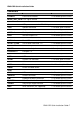
EMX-CDD Quick Installation Guide 2.3 Setting Jumpers & Connectors 2.3.1 Clear CMOS (JBAT1) Normal* Clear CMOS * Default 2.3.
EMX-CDD Quick Installation Guide 2.3.3 Jumper for COM2, IR selection (JIR1~2) IR* COM JIR2 JIR1 * Default Pin Define 1-2 COM 2-3 IR Note: IR is not functional. 2.3.
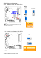
EMX-CDD Quick Installation Guide 2.3.5 Jumper for MPCIE_WIFI_SATA (JP1~4) SATA2* MINIPCIE JP4 JP3 JP2 JP1 M-SATA PIN Define * Default 1-2 MINIPCIE Note: SATA 2 bond together with M-SATA, it can only 2-3 M-SATA work either way at one time. 3-4 SATA2 2.3.6 Jumper for LVDS power (LVDS_PWR1) 5V* 3.3V * Default 10 EMX-CDD Quick Installation Guide Pin Define Max current 1-2 5V 1A 2-3 3.
EMX-CDD Quick Installation Guide 2.3.7 Jumper for inverter power (ADJ_PWR1) 5V* 0 5V * Default 2.3.
EMX-CDD Quick Installation Guide 2.3.9 Jumper for Serial port 1~6 selection (JC1~6) +5V JC6 JC5 JC4 JC3 JC2 JC1 +12V PIN Define Max current 1-2 +5V 1A 2-3 +12V 1A 2.3.
EMX-CDD Quick Installation Guide 2.3.11 General Purpose I/O (GPIO) Signal 2.3.
EMX-CDD Quick Installation Guide 2.3.13 LVDS connector (JLVDS1) Signal Note: Mapping connector DF13-40DS-1.25C (1.0mm).
EMX-CDD Quick Installation Guide 2.3.14 Printer (JLPT) Signal 2.3.15 PIN PIN Signal 25 SLCT GND 24 23 PE GND 22 21 BUSY GND 20 19 ACK GND 18 17 PD7 GND 16 15 PD6 GND 14 13 PD5 GND 12 11 PD4 GND 10 9 PD3 SLIN 8 7 PD2 INIT 6 5 PD1 ERR 4 3 PD0 AFD 2 1 STB VGA connector (JVGA) Signal PIN PIN Signal DDC_CLK 10 9 DDC_DATA VSYNC 8 7 HSYNC BLUE 6 5 GND GREEN 4 3 GND RED 2 1 GND Note: It can only use either D-SUB connector or Pin Header.
EMX-CDD Quick Installation Guide 2.3.16 2.3.17 Inverter connector (JINVERT1) PIN Signal Max current 1 12V 1A 2 GND 3 BLEN 4 PWM 5 5V 1A USB Connector 1~3 - USB2.
EMX-CDD Quick Installation Guide 2.3.18 Front Panel Audio Connection Header (F_AUDIO1) 2.3.
EMX-CDD Quick Installation Guide 2.3.20 2.3.
EMX-CDD Quick Installation Guide 2.3.22 SATA Power connector 1~2 (SATA1~2_PWR) SATA1_PWR SATA2_PWR P P 2.3.23 PIN Signal Max current 4 5V 1A 3 GND 2 GND 1 12V 1A Speaker Headers (JSPK) PIN Signal 4 INTSPR- 3 INTSPR+ 2 INTSPL- 1 INTSPL+ Note: Support 3W X 2 speaker.
EMX-CDD Quick Installation Guide 2.3.24 System Fan connector (SFAN1) 2.3.