EMX-PNV Intel® Atom™ PNV-M/ PNV-D Mini ITX Motherboard with Intel® ICH8-M Chipset Quick Installation Guide 1st Ed – September 1st 2010 Part No.
EMX-PNV Quick Installation Guide FCC Statement THIS DEVICE COMPLIES WITH PART 15 FCC RULES. OPERATION IS SUBJECT TO THE FOLLOWING TWO CONDITIONS: (1) THIS DEVICE MAY NOT CAUSE HARMFUL INTERFERENCE. (2) THIS DEVICE MUST ACCEPT ANY INTERFERENCE RECEIVED INCLUDING INTERFERENCE THAT MAY CAUSE UNDESIRED OPERATION. THIS EQUIPMENT HAS BEEN TESTED AND FOUND TO COMPLY WITH THE LIMITS FOR A CLASS "A" DIGITAL DEVICE, PURSUANT TO PART 15 OF THE FCC RULES.
EMX-PNV Quick Installation Guide detailed than the ones we can give over the phone. So please consult the user’s manual first. To receive the latest version of the user’s manual; please visit our Web site at: http://www.avalue.com.tw/ If you still cannot find the answer, gather all the information or questions that apply to your problem, and with the product close at hand, call your dealer. Our dealers are well trained and ready to give you the support you need to get the most from your Avalue’s products.
EMX-PNV Quick Installation Guide 1. Getting Started 1.1 Safety Precautions Warning! Always completely disconnect the power cord from your chassis whenever you work with the hardware. Do not make connections while the power is on. Sensitive electronic components can be damaged by sudden power surges. Only experienced electronics personnel should open the PC chassis. Caution! Always ground yourself to remove any static charge before touching the CPU card.
EMX-PNV Quick Installation Guide 2.
EMX-PNV Quick Installation Guide 2.
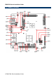
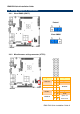
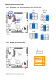
EMX-PNV Quick Installation Guide 2.2 Jumper and Connector List You can configure your board to match the needs of your application by setting jumpers. A jumper is the simplest kind of electric switch. It consists of two metal pins and a small metal clip (often protected by a plastic cover) that slides over the pins to connect them. To “close” a jumper you connect the pins with the clip. To “open” a jumper you remove the clip. Sometimes a jumper will have three pins, labeled 1, 2, and 3.
EMX-PNV Quick Installation Guide Connectors Label Function Note CN1 Speaker out connector 4 x 1 wafer, pitch 2.0mm CN2 USB connector 4 & 5 5 x 2 header, pitch 2.54 mm CN3 USB connector 6 & 7 5 x 2 header, pitch 2.54 mm CN4 SPI connector 3 x 2 header, pitch 2.0 mm CN5 Serial port 4 connector 5 x 2 header, pitch 2.54 mm CN6 LCD inverter connector 5 x 1 wafer, pitch 2.0mm CN7 Serial port 3 connector 5 x 2 header, pitch 2.54 mm CN8 CD-ROM Audio connector 4 x 1 wafer, pitch 2.
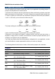
EMX-PNV Quick Installation Guide 2.3 Setting Jumpers & Connectors 2.3.1 Clear CMOS (JBAT1) Protect* Clear CMOS * Default 2.3.2 Miscellaneous setting connector (JFTP1) Signal Signal 1 2 SB_LED+ 3 4 GND +3.
EMX-PNV Quick Installation Guide 2.3.3 Serial port 3/ 4/ 2/ 1 pin 9 signal select (JP1/ JP2/ JP3/ JP4) JP3 JP4 JP1 JP2/ 3/ 4 Ring* Ring* +5V +5V +12V +12V JP1 JP2 * Default 2.3.
EMX-PNV Quick Installation Guide 2.3.5 USB connector 4 & 5/ 6 & 7 (CN2/ CN3) Signal CN2 CN3 2.3.6 PIN PIN Signal +5V 1 2 GND P4-/P6- 3 4 GND P4+/P6+ 5 6 P5+/P7+ GND 7 8 P5-/P7- GND 9 10 +5V SPI connector (CN4) Signal PIN PIN Signal +3.
EMX-PNV Quick Installation Guide 2.3.7 Serial port 4/ 3 connector (CN5/ CN7) CN5 CN7 Signal 2.3.8 PIN PIN Signal DCD 1 2 RxD TxD 3 4 DTR GND 5 6 DSR RTS 7 8 CTS RI 9 10 NC LCD backlight brightness adjustment (VR1) Signal PIN +5V 1 BRIGHT 2 GND 3 Variation Resistor (Recommended: 4.
EMX-PNV Quick Installation Guide 2.3.9 LCD Inverter Connector (CN6) Signal PIN +5V 5 BRIGHT 4 LBKLT_EN 3 GND 2 +12V 1 Note: For inverters with adjustable Backlight function, it is possible to control the LCD brightness through the VR signal controlled by VR1. Please see the VR1 section for detailed circuitry information. 2.3.9.1 Signal Description – LCD Inverter Connector (CN6) Signal Signal Description BRIGHT Vadj = 0.75V ~ 4.25V (Recommended: 4.
EMX-PNV Quick Installation Guide 2.3.10 CD-ROM Audio Connector (CN8) Signal PIN R 4 GND 3 L 2 GND 1 2.3.11 Front audio connector (CN9) Signal 14 EMX-PNV Quick Installation Guide PIN PIN Signal MIC2_L 1 2 GND MIC2_R 3 4 +3.
EMX-PNV Quick Installation Guide 2.3.
EMX-PNV Quick Installation Guide 2.3.13 CPU fan connector (CPU_FAN) FAN2 FAN1 FAN1 FAN2 Signal PIN GND 1 +12V 2 FAN_TAC1 3 2.3.14 VGA power connector (JVGA1) 16 EMX-PNV Quick Installation Guide Signal PIN PIN Signal GND 10 9 GND +12V 8 7 +12V +12V 6 5 +12V +3.3V 4 3 +3.
EMX-PNV Quick Installation Guide 2.3.15 VGA connector (JVGA2) Signal PIN PIN Signal HS 10 9 VS DAT 8 7 GND DCK 6 5 B GND 4 3 G +5V 2 1 R 2.3.
EMX-PNV Quick Installation Guide 2.3.17 LVDS connector (LVDS1) 18 EMX-PNV Quick Installation Guide Signal PIN PIN Signal NC 39 40 NC GND 37 38 GND NC 35 36 LVDSA_CLK- NC 33 34 LVDSA_CLK+ GND 31 32 GND NC 29 30 NC NC 27 28 NC GND 25 26 GND NC 23 24 NC NC 21 22 NC GND 19 20 GND NC 17 18 LVDSA_D2- NC 15 16 LVDSA_D2+ GND 13 14 GND LVDSA_D1- 11 12 LVDSA_D0- LVDSA_D1+ 9 10 LVDSA_D0+ GND 7 8 GND LCDSA_DDC_SC 5 6 LCDSA_DDC_SD +3.
EMX-PNV Quick Installation Guide 2.3.18 ATX power connector (PWR1) Signal PIN PIN Signal +3.3V 11 1 +3.3V -12V 12 2 +3.3V GND 13 3 GND PS_ON# 14 4 +5V GND 15 5 GND GND 16 6 +5V GND 17 7 GND NC 18 8 NC +5V 19 9 +5V +5V 20 10 +12V 2.3.
EMX-PNV Quick Installation Guide 2.3.