ENX-CDD Intel® Atom™ Cedar Trail Nano ITX Motherboard Intel® D2550 or N2800 + NM10 Chipset User’s Manual 3rd Ed – 25 January 2013 Copyright Notice Copyright 2013 Avalue Technology Inc., ALL RIGHTS RESERVED. Part No.
ENX-CDD User’s Manual Content 1. Getting Started ............................................................................................................ 4 1.1 Safety Precautions ........................................................................................... 4 1.2 Packing List ...................................................................................................... 4 1.3 Document Amendment History......................................................................... 5 1.
ENX-CDD User’s Manual 3.6.1.1 Intel RC Version ............................................................................ 30 3.6.1.2 System Language ......................................................................... 30 3.6.1.3 System Date ................................................................................. 30 3.6.1.4 System Time ................................................................................. 30 3.6.2 Advanced BIOS settings .............................................
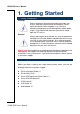
ENX-CDD User’s Manual 1. Getting Started 1.1 Safety Precautions Warning! Always completely disconnect the power cord from your chassis whenever you work with the hardware. Do not make connections while the power is on. Sensitive electronic components can be damaged by sudden power surges. Only experienced electronics personnel should open the PC chassis. Caution! Always ground yourself to remove any static charge before touching the CPU card.
ENX-CDD User’s Manual 1.
ENX-CDD User’s Manual 1.4 Manual Objectives This manual describes in details Avalue Technology ENX-CDD Single Board. We have tried to include as much information as possible but we have not duplicated information that is provided in the standard IBM Technical References, unless it proved to be necessary to aid in the understanding of this board. We strongly recommend that you study this manual carefully before attempting to set up ENX-CDD series or change the standard configurations.
ENX-CDD User’s Manual 1.
ENX-CDD User’s Manual 1 x 5-pin Header for Inverter 1 x CIR for remote control 1 x Powr on/off with Power LED button USB Parallel Port PS2 KB/MS DIO 3 x USB 2.0/1.
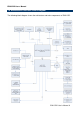
ENX-CDD User’s Manual 1.6 Architecture Overview—Block Diagram The following block diagram shows the architecture and main components of ENX-CDD.
ENX-CDD User’s Manual 2.
ENX-CDD User’s Manual 2.
ENX-CDD User’s Manual 12 ENX-CDD User’s Manual
ENX-CDD User’s Manual 2.2 Installation Procedure This chapter explains you the instructions of how to setup your system. 1. Turn off the power supply. 2. Insert the DIMM module (be careful with the orientation). 3. Insert all external cables for hard disk, floppy, keyboard, mouse, USB etc. except for flat panel. A CRT monitor must be connected in order to change BIOS settings to support flat panel. 4. Connect power supply to the board via the AC/DC Adapter. 5. Turn on the power. 6.
ENX-CDD User’s Manual 2.3 Jumper and Connector List You can configure your board to match the needs of your application by setting jumpers. A jumper is the simplest kind of electric switch. It consists of two metal pins and a small metal clip (often protected by a plastic cover) that slides over the pins to connect them. To “close” a jumper you connect the pins with the clip. To “open” a jumper you remove the clip. Sometimes a jumper will have three pins, labeled 1, 2, and 3.
ENX-CDD User’s Manual J3 Speaker connector 4 x 1 wafer, pitch 1.25 mm J4 SIM card holder JCOM1 Serial port 1 connector PWBT1 Power Button JGPIO1 General Purpose I/O 4 x 2 header, pitch 2.54 mm LPC Low Pin Count 5 x 2 header, pitch 2.00 mm LVDS1 LVDS connector 15 x 2 wafer, pitch 1.00 mm SATACON2 SATA AUX Board 12 x 1 wafer, pitch 1.00 mm JUSB1 USB connector 4 x 1 wafer, pitch 1.
ENX-CDD User’s Manual 2.4 Setting Jumpers & Connectors 2.4.1 LVDS voltage (JP1) VCC5* VCC3 Pin Define 1-2 VCC3 2-3 VCC5 * Default 2.4.
ENX-CDD User’s Manual 2.4.3 2.4.4 LCD Inverter connector (INCN1) Signal PIN 5V 5 PWM 4 BKL_EN 3 GND 2 12V 1 General Purpose I/O (JGPIO1) Signal PIN PIN Signal GND 8 7 GND GPIO 6 5 GPIO GPIO 4 3 GPIO 3.
ENX-CDD User’s Manual 2.4.5 VGA connector (JVGA1) Signal 2.4.
ENX-CDD User’s Manual 2.4.7 System Fan connector (SFAN1) 2.4.
ENX-CDD User’s Manual 2.4.9 Keyboard & mouse connector (JKB_MS1) Signal PIN PIN Signal MS_CLK 1 2 MS_DATA KB_CLK 3 4 KB_DATA VCC 5 6 GND Note: The KB/Mouse cable is not included. 2.4.
ENX-CDD User’s Manual 2.4.11 SATA AUX Board (SATACON2) Note: To SATA AUX board. Signal PIN NC 1 +5V 2 +5V 3 +5V 4 GND 5 GND 6 RXP 7 RXN 8 GND 9 TXN 10 TXP 11 GND 12 2.4.
ENX-CDD User’s Manual 2.4.13 LVDS connector (LVDS1) Signal PIN PIN Signal VDD 30 29 VDD VDD 28 27 VDD DDC_CLK 26 25 GND DDC_DATA 24 23 DATA3- GND 22 21 DATA3+ CLKN 20 19 GND CLKP 18 17 DATA2- Recommend connector. GND 16 15 DATA2+ On board LVDS connector: CSI-1171-30. GND 14 13 GND GND 12 11 GND DATA1- 10 9 DATA0- DATA1+ 8 7 DATA0+ GND 6 5 GND GND 4 3 PWM GND 2 1 GND Note: Matting connector:KB901-B30H.
ENX-CDD User’s Manual 2.4.14 USB connector (JUSB1) Signal PIN +5VSB 1 DATAN 2 DATAP 3 GND 4 Signal PIN BAT 1 GND 2 2.4.
ENX-CDD User’s Manual 2.4.16 PCIE signal selector (J_PCIE) Signal PIN RXN 14 RXP 13 GND 12 TXN 11 TXP 10 GND 9 CLKP 8 CLKN 7 RESET 6 WAKE 5 +5VSB 4 +5VSB 3 GND 2 +3.3V 1 Note: For Customized add-on card, the expansion card is not included.
ENX-CDD User’s Manual 3.
ENX-CDD User’s Manual 3.1 Introduction The BIOS setup program allows users to modify the basic system configuration. In this following chapter will describe how to access the BIOS setup program and the configuration options that may be changed. 3.2 Starting Setup The BIOS is immediately activated when you first power on the computer. The BIOS reads the system information contained in the NVRAM and begins the process of checking out the system and configuring it.
ENX-CDD User’s Manual 3.3 Using Setup In general, you use the arrow keys to highlight items, press to select, use the PageUp and PageDown keys to change entries, press for help and press to quit. The following table provides more detail about how to navigate in the Setup program using the keyboard.
ENX-CDD User’s Manual 3.4 Getting Help Press F1 to pop up a small help window that describes the appropriate keys to use and the possible selections for the highlighted item. To exit the Help Window press or the F1 key again. 3.5 In Case of Problems If, after making and saving system changes with Setup, you discover that your computer no longer is able to boot, the AMI BIOS supports an override to the NVRAM settings which resets your system to its defaults.
ENX-CDD User’s Manual 3.6 BIOS setup Once you enter the BIOS Setup Utility, the Main Menu will appear on the screen. The Main Menu allows you to select from several setup functions and exit choices. Use the arrow keys to select among the items and press to accept and enter the sub-menu. 3.6.1 Main Menu This section allows you to record some basic hardware configurations in your computer and set the system clock.
ENX-CDD User’s Manual 3.6.1.1 Intel RC Version Intel Reference Code version. 3.6.1.2 System Language Use this option to select system language 3.6.1.3 System Date Use the system date option to set the system date. Manually enter the day, month and year. 3.6.1.4 System Time Use the system time option to set the system time. Manually enter the hours, minutes and seconds. Note: BIOS setup screens shown in this chapter are for reference only, and may not exactly match what you see on your screen.
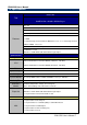
ENX-CDD User’s Manual 3.6.2 Advanced BIOS settings This section allows you to configure your CPU and other system devices for basic operation through the following sub-menus. 3.6.2.1 ACPI Settings You can use this item to set up ACPI Configuration. Item Options Description Enable Hibernation Disabled, Enabled[Default] Enables or Disables System ability to Hibernate (OS/S4 Sleep State). This option may be not effective with some OS.
ENX-CDD User’s Manual ACPI Sleep State S1 (CPU Stop Clock) [Default] S3 (Suspend to RAM) Select the highest ACPI sleep state the system will enter when the SUSPEND button is pressed. 3.6.2.2 CPU Configuration Use the CPU configuration menu to view detailed CPU specification and configure the CPU.
ENX-CDD User’s Manual 3.6.2.3 Onboard Device Configuration Item Azalia Controller USB Function USB 2.0(EHCI) Support LAN Controller Launch PXE OpROM Options HD Audio[Default] Disabled Enabled[Default] Disabled Enabled[Default] Disabled Enabled[Default] Disabled Enabled Disabled[Default] Description Azalia Controller. Enable/Disable USB Function. Enable or Disable USB 2.0(EHCI) Support. Enable or Disable OnChip NIC Controller. Enable or Disable Boot Option for Legacy Network Devices.
ENX-CDD User’s Manual 3.6.2.4 USB Configuration The USB configuration menu is used to read USB configuration information and configure USB. Item Options Legacy USB Support Enabled[Default] Disabled Auto ECHI Hand-Off Enabled Disabled[Default] USB transfer time-out Device reset time-out 1sec / 5sec 10sec / 20sec[Default] 10sec / 20sec[Default] 30sec / 40sec Device power-up delay 34 ENX-CDD User’s Manual Auto[Default] Manual Description Enables Legacy USB support.
ENX-CDD User’s Manual 3.6.2.5 Super IO Configuration You can use this item to set up or change the Super IO configuration for FDD controllers, parallel ports and serial ports. Item Serial Port 0 Configuration WatchDogTimer Options Description Set Parameters of Serial Port0 (COMA). Enabled Disabled[Default] WatchDogTimer Setting. 3.6.2.5.
ENX-CDD User’s Manual Item Serial Port Change Settings Option Enabled, Disabled[Default] Auto[Default] IO=3F8h; IRQ=4; IO=3F8h; IRQ=3,4,5,6,7,9.10,11,12 IO=2F8h; IRQ=3,4,5,6,7,9.10,11,12 Description Enable or Disable Serial Port (COM). Select an optimal setting for Super IO device. 3.6.2.6 W83627UHG HW Monitor The H/W Monitor shows the operating temperature, fan speeds and system voltages. 3.6.2.
ENX-CDD User’s Manual Item Options Description PS2 KB/MS Wakeup Function Disabled[Default] Enabled Wakeup System from S1/S3 by PS2 KB and PS2 KeyBoard PowerOn Disabled[Default] Enabled USB Wakeup Function Disabled Enabled[Default] LAN Wakeup Function Restore AC Power Loss Disabled Enabled[Default] Power Off Power On Last State[Default] MS. Power On System by PS2 KB. Wakeup System from S1/S3 by USB KB and MS. Wakeup System from S3/S5 by LAN.
ENX-CDD User’s Manual 3.6.3.1 Host bridge 3.6.3.1.1 Intel IGD Configuration Item IGFX – Boot Type Active LFP 38 ENX-CDD User’s Manual Option VBIOS Default[Default] CRT LFP EFP CRT+LFP CRT+EFP LFP+EFP Disabled Enable LVDS[Default] Description Select the Video Device which will be activated during POST. This has no effect if external graphics present. Enable or Disable LVDS.
ENX-CDD User’s Manual LCD Panel Type Backlight Control Fixed Graphics Memory Size Backlight Control Support VBIOS Default 640x480 18/1 800x600 18/1 1024x768 18/1[Default] 1024x768 24/1 1366x768 24/1 1280x800 18/1 1024x600 18/1 PWM Inverted PWM Normal[Default] 128 MB[Default] 256 MB VBIOS-Default[Default] BLC&BIA Disabled BLC Enabled Select LCD panel used by Internal Graphics Device by selecting the appropriate setup item. Back Light Control Setting. Configure Fixed Graphics Memory Size.
ENX-CDD User’s Manual SATA Port 1 SATA Port 1 Hot Plug 3.6.4 Enabled[Default], Disabled Enabled[Default], Disabled Enable or Disable SATA Port. Designates this port as Hot Pluggable. Boot settings Item Setup Prompt Timeout Bootup NumLock State Quiet Boot Fast Boot 40 ENX-CDD User’s Manual Option 1~65535 On[Default] Off Enabled Disabled[Default] Enabled[Default] Disabled Description Number of seconds to wait for setup activation key. 65535(0xFFFF) means indefinite waiting.
ENX-CDD User’s Manual 3.6.5 Security Use the Security menu to set system and user password. 3.6.5.1 Administrator Password This setting specifies a password that must be entered to access the BIOS Setup Utility. If only the Administrator's password is set, then this only limits access to the BIOS setup program and is only asked for when entering the BIOS setup program. By default, no password is specified. 3.6.5.
ENX-CDD User’s Manual 3.6.6 Save & Exit 3.6.6.1 Save Changes and Reset Any changes made to BIOS settings are stored in NVRAM. The setup program then exits and reboots the controller.
ENX-CDD User’s Manual 3.6.6.2 Discard Changes and Reset Any changes made to BIOS settings during this session of the BIOS setup program are discarded. The setup program then exits and reboots the controller. 3.6.6.3 Restore Defaults This option restores all BIOS settings to the factory default. This option is useful if the controller exhibits unpredictable behavior due to an incorrect or inappropriate BIOS setting. 3.6.6.
ENX-CDD User’s Manual 4. Drivers Installation Note: Installation procedures and screen shots in this section are for your reference and may not be exactly the same as shown on your screen.
ENX-CDD User’s Manual 4.1 Install Audio Driver (For Realtek ALC661 HD Audio) Insert the Supporting DVD-ROM to DVD-ROM drive, and it should show the index page of Avalue’s products automatically. If not, locate Index.htm and choose the product from the menu left, or link to \ Driver_Audio\ENX-CDD_Audio Note: The installation procedures and screen shots in this section are based on Windows 7 operation system. If the warning message appears while the installation process, click Continue to go on. Step1.
ENX-CDD User’s Manual 4.2 Install Chipset Driver (For Integrated Cedar Trail) Insert the Supporting DVD-ROM to DVD-ROM drive, click on “start” icon and it should show the index page of Avalue’s products automatically. If not, locate the folder HTML and choose the product from the targeted folder. Note: The installation procedures and screen shots in this section are based on Windows 7 operating system. Step 1. Locate 「\ Driver_Chipset\ENX-CDD_Chipset」. Step 2. Select Next to start setup. Step 3.
ENX-CDD User’s Manual 4.3 Install VGA Driver Insert the Supporting DVD-ROM to DVD-ROM drive, click on “start” icon and it should show the index page of Avalue’s products automatically. If not, locate the folder HTML and choose the product from the targeted folder. Note: The installation procedures and screen shots in this section are based on Windows 7 operating system. Step 1. Locate「\VGA\ENX-CDD_Graphics」. Step 4. Select Next to continue installation. Step 2. Select Next to start setup. Step 5.
ENX-CDD User’s Manual 4.4 Install LAN Driver (For Realtek 8111E Gigabit Ethernet) Insert the Supporting DVD-ROM to DVD-ROM drive, and it should show the index page of Avalue’s products automatically. If not, locate Index.htm and choose the product from the menu left, or link to \Driver_Network\ENX-CDD_LAN. Note: The installation procedures and screen shots in this section are based on Windows 7 operation system. Step 1. Click Next to Install. Step 2. Click Install to begin the installation.
ENX-CDD User’s Manual 4.5 Install AHCI Driver Insert the Supporting DVD-ROM to DVD-ROM drive, click on “start” icon and it should show the index page of Avalue’s products automatically. If not, locate the folder HTML and choose the product from the targeted folder. Note: The installation procedures and screen shots in this section are based on Windows 7 operating system. Step 1. Locate 「\Utility\ENX-CDD_AHCI」. Step 2. Select Next to start setup. Step 3. Select Yes to the next step. Step 4.
ENX-CDD User’s Manual 4.6 Install Cardreader Driver Insert the Supporting DVD-ROM to DVD-ROM drive, and it should show the index page of Avalue’s products automatically. If not, locate Index.htm and choose the product from the menu left, or link to \Utility\Cardreader. Note: The installation procedures and screen shots in this section are based on Windows 7 operation system. Step 3. Click Finish to complete setup. Step 1. Preparing Setup. Step 2. Installation.
ENX-CDD User’s Manual 4.7 Install CIR Driver Insert the Supporting DVD-ROM to DVD-ROM drive, and it should show the index page of Avalue’s products automatically. If not, locate Index.htm and choose the product from the menu left, or link to \Utility\CIR. Note: The installation procedures and screen shots in this section are based on Windows 7 operation system. Step 3. Click Finish to complete setup. Step 1. Click Next to Install. Step 2. Click Install to begin the installation.
ENX-CDD User’s Manual 5.
ENX-CDD User’s Manual Unit: mm ENX-CDD User’s Manual 53
ENX-CDD User’s Manual Unit: mm 54 ENX-CDD User’s Manual