EPC-KA Fanless AMD G-Series SoC Tiny Box PC Quick Reference Guide 1st Ed – 18 June 2014 Copyright Notice Copyright 2014 Avalue Technology Inc., ALL RIGHTS RESERVED. Part No.
EPC-KA FCC Statement THIS DEVICE COMPLIES WITH PART 15 FCC RULES. OPERATION IS SUBJECT TO THE FOLLOWING TWO CONDITIONS: (1) THIS DEVICE MAY NOT CAUSE HARMFUL INTERFERENCE. (2) THIS DEVICE MUST ACCEPT ANY INTERFERENCE RECEIVED INCLUDING INTERFERENCE THAT MAY CAUSE UNDESIRED OPERATION. THIS EQUIPMENT HAS BEEN TESTED AND FOUND TO COMPLY WITH THE LIMITS FOR A CLASS "A" DIGITAL DEVICE, PURSUANT TO PART 15 OF THE FCC RULES.
Quick Reference Guide Content 1. Getting Started ............................................................................................................ 4 1.1 1.2 1.3 1.4 1.4.1 Front View ................................................................................................................................ 7 1.4.2 Rear View ................................................................................................................................ 8 1.5 1.5.1 2. Safety Precautions .
EPC-KA 1. Getting Started 1.1 Safety Precautions Warning! Always completely disconnect the power cord from your chassis whenever you work with the hardware. Do not make connections while the power is on. Sensitive electronic components can be damaged by sudden power surges. Only experienced electronics personnel should open the PC chassis. Caution! Always ground yourself to remove any static charge before touching the CPU card. Modern electronic devices are very sensitive to static electric charges.
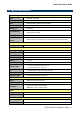
Quick Reference Guide 1.3 System Specifications System Board ECM-KA + AUX-032 CPU AMD GX-415GA 1.5GHz SoC BIOS AMI uEFI BIOS, 32Mbit SPI Flash ROM System Chipset AMD SoC Integrated I/O Chipset IT8518VG One 204-pin DDR3 SODIMM Socket Supports Up to 8GB DDR3 1600 System Memory SDRAM (Default 2GB) Reset: 1sec. ~ 65535sec.
EPC-KA Mechanical +12~26Vdc (Lockable DC Jack) Single Power ATX Support S0, S3, S5 ACPI 3.0 Compliant Power Mode AT/ATX (ATX is the default setting) Operating 0 ~ 50°C (32 ~ 122°F) (w/CF & SSD), Ambient w/Air Flow Temperature 0 ~ 40°C (32 ~ 104°F) (w/HDD), Ambient w/Air Flow -40 ~ 75°C (-40 ~ 167°F) 0% ~ 90% Relative Humidity, Non-condensing With CF/SSD: 1.
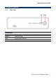
Quick Reference Guide 1.4 System Overview 1.4.1 Front View Connectors Label Function POWER Power on button LED System power indicator USB USB 2.
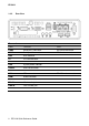
EPC-KA 1.4.2 Rear View Connectors Label Function Note COM1 Serial port 1 connector DB-9 male connector COM2 Serial port 2 connector DB-9 male connector HDD HDD indicator CF CF card connector LAN RJ-45 Ethernet PWR System power indicator USB2.0 USB 2.0 connector USB3.0 USB 3.
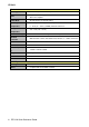
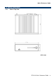
Quick Reference Guide 1.5 System Dimensions 1.5.
EPC-KA 2. Hardware Configuration For advanced information, please refer to: 1- ECM-KA Quick Installation Guide or User’s Manual 2- AUX-032 included in this manual. Note: If you need more information, please visit our website: http://www.avalue.com.
Quick Reference Guide 2.1 EPC-KA connector mapping 2.1.1 2.1.
EPC-KA 2.1.
Quick Reference Guide 2.2 AUX-032 User’s Guide 2.2.1 Jumper and Connector Layout 2.2.2 Jumper and Connector List Connectors Label Function Note CN1/2 USB connector CN4 Line out connector Phone Jack CN5 Line in connector Phone Jack CN6 Mic in connector Phone Jack JAUDIO Audio connector 6 x 2 header, pitch 2.0mm JP1 2.54mm USB connector 5 x 2 header, pitch 2.54mm JP2 2.54mm USB connector 5 x 2 header, pitch 2.54mm JP4 2.0mm USB connector 5 x 2 header, pitch 2.0mm JP5 2.
EPC-KA 2.2.3 Setting Jumper and Connector Audio Connector (JAUDIO) Signal PIN PIN 2.54mm USB Connector (JP1) Signal Signal PIN PIN Signal OUTR 1 2 OUTL +5V 1 2 GND GND 3 4 GND D1- 3 4 GND INR1 5 6 INL1 D1+ 5 6 D2+ MICIN1 7 8 AREF GND 7 8 D2- FRONT-JD1 9 10 LINE1-JD1 GND 9 10 +5V MIC1-JD1 11 12 GND Note: Wrong USB cable configuration with your USB devices might damage your USB devices. 2.
Quick Reference Guide 2.3 Installing Hard Disk & Memory (EPC-KA) Step1. Remove the screw from the bottom before removing back cover. Step2. Insert CF card into CF slot.
EPC-KA Step3. For HDD installation, please remove 4 screws to detach top cover, HDD enclosure from board & system assembly. Step4. Fix HDD using the 4 screws in the Accessory Kit.
Quick Reference Guide Step5.1 Properly install the memory module and press until properly seated. Step5.2 Re-assemble your system back through previous steps to complete the installation.