EPI-LX800 Series AMD Geode GX3 EPIC Module Quick Installation Guide 1st Ed – 08 August 2006 To receive the latest version of the user’s manual; please visit our Web site at: http://www.avalue.com.tw Copyright Notice Copyright © 2007 Avalue Technology Inc., ALL RIGHTS RESERVED. Part No.
EPI-LX800 Series Contents 1. Getting Started............................................................................................................3 1.1 Safety Precautions ................................................................................................3 1.2 Packing List ...........................................................................................................3 2. Hardware Configuration...................................................................................
Quick Installation Guide 1. Getting Started 1.1 Safety Precautions Warning! Always completely disconnect the power cord from your chassis whenever you work with the hardware. Do not make connections while the power is on. Sensitive electronic components can be damaged by sudden power surges. Only experienced electronics personnel should open the PC chassis. Caution! Always ground yourself to remove any static charge before touching the CPU card.
EPI-LX800 Series 2.
Quick Installation Guide 2.
EPI-LX800 Series 2.2 Jumper and Connector List You can configure your board to match the needs of your application by setting jumpers. A jumper is the simplest kind of electric switch. It consists of two metal pins and a small metal clip (often protected by a plastic cover) that slides over the pins to connect them. To “close” a jumper you connect the pins with the clip. To “open” a jumper you remove the clip. Sometimes a jumper will have three pins, labeled 1, 2, and 3.
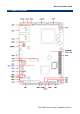
Quick Installation Guide Connectors Label Function Note CN1 ATX power connector CN2 Parallel port connector CN3 PCI-104 connector CN4 4/5/8-wire touch screen connector (Optional) CN5 RJ-45 Ethernet / USB 2 & 3 connector CN6 RJ-45 Ethernet / USB 0 & 1 connector CN7 Audio connector Phone jack x 3 CN8 VGA connector D-sub 15-pin, female COM1 Serial port 1 connector 5 x 2 header, pitch 2.0mm COM2 Serial port 2 connector 5 x 2 header, pitch 2.
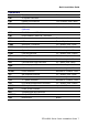
EPI-LX800 Series 2.3 Setting Jumpers & Connectors 2.3.1 Clear CMOS (JBAT) Protect* Clear CMOS * Default 2.3.2 PCI-104 Voltage Select (JP2) +5V* +3.
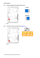
Quick Installation Guide 2.3.3 COM1 Pin 9 Signal Select (JP3) +5V Ring* +12V * Default 2.3.
EPI-LX800 Series 2.3.5 Speaker/Headphone Audio Output Select (JP6) Speaker* Headphone * Default 2.3.
Quick Installation Guide 2.3.
EPI-LX800 Series 2.3.8 AT/ATX Power Select (SW2) (Bit 6) AT* ATX * Default 2.3.
Quick Installation Guide 2.3.10 2.3.
EPI-LX800 Series 2.3.12 2.3.
Quick Installation Guide 2.3.14 LCD Inverter Connector (JBKL) Signal PIN +12V 1 GND 2 ENBKL 3 VR 4 +5V 5 Note: For inverters with adjustable Backlight function, it is possible to control the LCD brightness through the VR signal controlled by JVR. Please see the JVR section for detailed circuitry information. 2.3.14.1 Signal Description – LCD Inverter Connector (JBKL) Signal Signal Description VR Vadj = 0.75V ~ 4.25V (Recommended: 4.
EPI-LX800 Series 2.3.16 2.3.
Quick Installation Guide 2.3.18 LVDS Connector (JLVDS) Signal PIN PIN Signal +5V 2 1 +3.3V +5V 4 3 2 +3.3V 2 I C_DAT 6 5 I C_CLK GND 8 7 GND Txout0 10 9 Txout1 Txout0# 12 11 Txout1# GND 14 13 GND Txout2 16 15 Txout3 Txout2# 18 17 Txout3# GND 20 19 GND NC 22 21 NC NC 24 23 NC GND 26 25 GND NC 28 27 NC NC 30 29 NC GND 32 31 GND Txclk 34 33 NC Txclk# 36 35 NC GND 38 37 GND +12V 40 39 +12V 2.3.18.
EPI-LX800 Series 2.3.19 2.3.
Quick Installation Guide 2.3.21 TFT Panel Connector (JTFT) Signal PIN PIN Signal +5V 2 1 +5V GND 4 3 GND +3.3V 6 5 +3.3V GND 8 7 NC P1 10 9 P0 P3 12 11 P2 P5 14 13 P4 P7 16 15 P6 P9 18 17 P8 P11 20 19 P10 P13 22 21 P12 P15 24 23 P14 P17 26 25 P16 P19 28 27 P18 P21 30 29 P20 P23 32 31 P22 GND 34 33 GND FLM 36 35 SHFCLK LP 38 37 M NC 40 39 ENBKL 2.3.21.
EPI-LX800 Series 2.3.21.2 Signal Description – TFT Panel Display (JTFT) Signal P0 P1 P2 P3 P4 P5 P6 P7 P8 P9 P10 P11 P12 P13 P14 P15 P16 P17 P18 P19 P20 P21 P22 P23 2.3.22 18-bit TFT B0 B1 B2 B3 B4 B5 G0 G1 G2 G3 G4 G5 R0 R1 R2 R3 R4 R5 24-bit TFT B0 B1 B2 B3 B4 B5 B6 B7 G0 G1 G2 G3 G4 G5 G6 G7 R0 R1 R2 R3 R4 R5 R6 R7 LCD Backlight Brightness Adjustment Connector (JVR) JVR Signal PIN +5V 1 VR 2 GND 3 VCC 1 JBKL pin 4 2 3 Variation Resistor (Recommended: 4.