EPS Series EPS-QM67/EPS-QM77E Fanless Intel® Core™ i7/ i5/ i3/ Cerlon Rugged Embedded System with Intel® QM67 Chipset /Fanless Intel® CoreTM i7/ i5/ i3 Rugged Embedded System with Intel® QM77 Quick Reference Guide 1ST Ed –4 December 2012 Copyright Notice Copyright 2012 Avalue Technology Inc., ALL RIGHTS RESERVED. Part No.
EPS Series 1. Getting Started 1.1 Safety Precautions Warning! Always completely disconnect the power cord from your chassis whenever you work with the hardware. Do not make connections while the power is on. Sensitive electronic components can be damaged by sudden power surges. Only experienced electronics personnel should open the PC chassis. Caution! Always ground yourself to remove any static charge before touching the CPU card. Modern electronic devices are very sensitive to static electric charges.
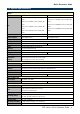
Quick Reference Guide 1.3 System Specifications System Model EPS-QM67 EPS-QM77E Intel® Core™ i7-2710QE, 2-Core, 2.1GHz, 6M CPU Cache Intel® Core™ i7-3610QE, 4-Core, 2.3GHz, 3M Intel® Core™ i5-2510E, 2-Core, 2.5GHz, 3M Cache Cache Intel® Core™ i5-3610ME, 2-Core, 2.7GHz, 3M Intel® Core™ i3-2330E, 2-Core, 2.2GHz, 3M Cache Cache Intel® Core™ i3-3120ME, 2-Core, 2.4GHz, 3M Intel® Celeron® B810, 2-Core, 1.
EPS Series Shock Protection Size (L x W x H) Weight Mounting 4 With SSD: 50G, IEC 60068-2-27, Half Sine,11ms 250mm x 220mm x 60mm 7.7lbs (3.
Quick Reference Guide 1.4 System Overview 1.4.
EPS Series 1.4.2 Rear View EPS-QM67 EPS-QM77E Connectors Label Function COM1~2 Serial port connector1~2 DC-IN DC power-in connector (lockable DC Jack) HDD HDD Indicator PWR Power Indicator LAN1 RJ-45 Ethernet 1 LAN2 RJ-45 Ethernet 2 LINE IN Line-in audio jack LINE OUT Line-out audio jack MIC IN Microphone-in audio jack Power System power switch HDMI HDMI connector DVI DVI connector USB1~6 USB 2.0 connector 1~6 (EPS-QM67) USB1~2 USB 2.
Quick Reference Guide 2. Hardware Configuration Jumper and Connector Setting, Driver and BIOS Installing For advanced information, please refer to: 1- EPI-QM67 Quick Installation Guide or User’s Manual 2- EPI-QM77 Quick Installation Guide or User’s Manual Note: If you need more information, please visit our website: http://www.avalue.com.
EPS Series 2.1 EPS Series connector mapping 2.2.1 2.2.
Quick Reference Guide 2.2 Installing Hard Disk & Memory (EPS-QM67) Step 1. Remove 8 screws from the bottom of your system. Step 2. Remove the chassis cover. Step 1. Slide HDD into its bracket until properly seated. Step 2. Secure HDD by means of 4 screws. Step 3. Connect necessary cables to the HDD. Step 4. Slide the DDR3 SODIMM into the memory socket and press it down until properly seated.
EPS Series 2.3 Installing Hard Disk & Memory (EPS-QM77E) Step 1. Remove 8 screws from the bottom of your system. Step 2. Remove the chassis cover. Step 1. Slide HDDs into its bracket until properly seated. Step 2. Secure HDDs by means of 8 screws (4 for each). Step 3. Connect necessary cables to HDDs. Step 4. Slide the DDR3 SODIMM into the memory socket and press it down until properly seated.
Quick Reference Guide 2.4 Installing Mounting Brackets (EPS Series) Step 1. Remove 8 screws from the back of your system to install brackets. Step 2. Locate brackets on both sides, matching the holes on the system. Step 3. Insert and fasten 4 screws on each side of the system to secure Mounting brackets.
EPS Series Step 4. Installation completed.