EQM-BYT Intel® Atom™ SoC Processors Qseven Module Quick Installation Guide 1st Ed – 26 February 2014 Notice This guide is designed for experienced users to setup the system within the shortest time. For detailed information, please always refer to the electronic user's manual. Copyright Notice Copyright 2014 Avalue Technology Inc., ALL RIGHTS RESERVED. Part No.
EQM-BYT Content 1. Getting Started ........................................................................................................... 3 1.1 Safety Precautions ................................................................................................ 3 1.2 Packing List ................................................................................................................ 3 2. Hardware Configuration ....................................................................................
Quick Installation Guide 1. Getting Started 1.1 Safety Precautions Warning! Always completely disconnect the power cord from your chassis whenever you work with the hardware. Do not make connections while the power is on. Sensitive electronic components can be damaged by sudden power surges. Only experienced electronics personnel should open the PC chassis. Caution! Always ground yourself to remove any static charge before touching the CPU card.
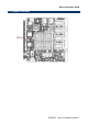
EQM-BYT 2.
Quick Installation Guide 2.
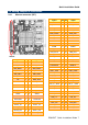
EQM-BYT 2.2 Jumper and Connector List You can configure your board to match the needs of your application by setting jumpers. A jumper is the simplest kind of electric switch. It consists of two metal pins and a small metal clip (often protected by a plastic cover) that slides over the pins to connect them. To “close” a jumper you connect the pins with the clip. To “open” a jumper you remove the clip. Sometimes a jumper will have three pins, labeled 1, 2, and 3.
Quick Installation Guide 2.3 Setting Jumpers & Connectors 2.3.
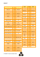
EQM-BYT Signal PIN PIN Signal Signal PIN PIN Signal LVDS_A1- 105 106 LVDS_B1- UART_TX 171 172 UART_RTS LVDS_A2+ 107 108 LVDS_B2+ PCIE1_TX+ 173 174 PCIE1_RX+ LVDS_A2- 109 110 LVDS_B2- PCIE1_TX- 175 176 PCIE1_RX- LVDS_PPEN 111 112 LVDS_BLEN UART_RX 177 178 UART_CTS LVDS_A3+ 113 114 LVDS_B3+ PCIE0_TX+ 179 180 PCIE0_RX+ LVDS_A3- 115 116 LVDS_B3- PCIE0_TX- 181 182 PCIE0_RX- GND15 117 118 GND16 GND27 183 184 GND28 LVDS_A_CLK+ 119 120 LVDS_B_CLK+ LPC_AD0 185 186