ESM-BYT Intel® Atom™ SoC Processors COM Express Type 6 Module User’s Manual 1st Ed – 18 August 2014 Copyright Notice Copyright 2014 Avalue Technology Inc., ALL RIGHTS RESERVED. Part No.
ESM-BYT User’s Manual FCC Statement THIS DEVICE COMPLIES WITH PART 15 FCC RULES. OPERATION IS SUBJECT TO THE FOLLOWING TWO CONDITIONS: (1) THIS DEVICE MAY NOT CAUSE HARMFUL INTERFERENCE. (2) THIS DEVICE MUST ACCEPT ANY INTERFERENCE RECEIVED INCLUDING INTERFERENCE THAT MAY CAUSE UNDESIRED OPERATION. THIS EQUIPMENT HAS BEEN TESTED AND FOUND TO COMPLY WITH THE LIMITS FOR A CLASS “A” DIGITAL DEVICE, PURSUANT TO PART 15 OF THE FCC RULES.
ESM-BYT User’s Manual these products are free from patent, copyright, or mask work right infringement, unless otherwise specified. Applications that are described in this manual are for illustration purposes only. Avalue Technology Inc. makes no representation or warranty that such application will be suitable for the specified use without further testing or modification.
ESM-BYT User’s Manual CONTENT 1. Getting Started ............................................................................................................ 7 1.1 Safety Precautions .................................................................................................... 7 1.2 Packing List ............................................................................................................... 7 1.3 Document Amendment History ...............................................................
ESM-BYT User’s Manual 2.4.3.1.2 DDI Signals .......................................................................................................................... 33 3.BIOS Setup .................................................................................................................... 34 3.1 Introduction ............................................................................................................. 35 3.2 Starting Setup ...........................................................
ESM-BYT User’s Manual 3.6.3.2.3 PCI Express Configuration .................................................................................................... 63 3.6.4 Security ......................................................................................................................................... 63 3.6.4.1 Secure Boot menu ............................................................................................................... 64 3.6.5 Boot ......................................
ESM-BYT User’s Manual 1. Getting Started 1.1 Safety Precautions Warning! Always completely disconnect the power cord from your chassis whenever you work with the hardware. Do not make connections while the power is on. Sensitive electronic components can be damaged by sudden power surges. Only experienced electronics personnel should open the PC chassis. Caution! Always ground yourself to remove any static charge before touching the CPU card.
ESM-BYT User’s Manual 1.
ESM-BYT User’s Manual 1.4 Manual Objectives This manual describes in details Avalue Technology ESM-BYT Single Board. We have tried to include as much information as possible but we have not duplicated information that is provided in the standard IBM Technical References, unless it proved to be necessary to aid in the understanding of this board. We strongly recommend that you study this manual carefully before attempting to set up ESM-BYT series or change the standard configurations.
ESM-BYT User’s Manual 1.
ESM-BYT User’s Manual ACPI Power Type Operating Temp. Storage Temp. Single power ATX Support S0, S3, S4, S5 ACPI 3.0 Compliant AT/ATX Standard: 0 to 60C Extended: -40 to 85C -55°C to 85°C Operating Humidity 0% ~ 90% relative humidity, non-condensing Size (L x W) Weight 125 mm x 95 mm 0.44lbs(0.
ESM-BYT User’s Manual 1.6 Architecture Overview—Block Diagram The following block diagram shows the architecture and main components of ESM-BYT.
ESM-BYT User’s Manual 2.
ESM-BYT User’s Manual 2.
ESM-BYT User’s Manual ESM-BYT User’s Manual 15
ESM-BYT User’s Manual 2.2 Installation Procedure This chapter explains you the instructions of how to setup your system. 1. Turn off the power supply. 2. Insert the DIMM module (be careful with the orientation). 3. Insert all external cables for hard disk, keyboard, mouse, USB etc. except for flat panel. A CRT monitor must be connected in order to change NVRAM settings to support flat panel. 4. Connect power supply to the board via the ATXPWR. 5. Turn on the power. 6.
ESM-BYT User’s Manual 2.2.1 Main Memory ESM-BYT provides two 204-pin SODIMM socket, supports up to 8GB DDR3L 1066/1333 SDRAM, DIMM1 must be inserted when only a single memory is used. SODIMM Make sure to unplug the power supply before adding or removing DIMMs or other system components. Failure to do so may cause severe damage to board and components.
ESM-BYT User’s Manual Locate the SODIMM socket on the board. Carefully hold two edges of the SODIMM module. avoid touching its connectors. Align the notch key on the module with the rib on the slot. Firmly press the modules into the socket which automatically snaps into the mounting notch. Do not force the SODIMM module in with extra force as the SODIMM module only fits in one direction.
ESM-BYT User’s Manual 2.3 Connector List You can configure your board to match the needs of your application by setting jumpers. A jumper is the simplest kind of electric switch. It consists of two metal pins and a small metal clip (often protected by a plastic cover) that slides over the pins to connect them. To “close” a jumper you connect the pins with the clip. To “open” a jumper you remove the clip. Sometimes a jumper will have three pins, labeled 1, 2, and 3.
ESM-BYT User’s Manual 2.4 Setting Jumpers & Connectors 2.4.1 AT/ATX mode selector (SW1) AT/ATX mode AT mode* OFF 1 ON 2 ATX mode OFF 1 ON 2 *Default 2.4.1.
ESM-BYT User’s Manual 2.4.
ESM-BYT User’s Manual Signal PIN PIN Signal GND A31 B31 GND AC/HDA_BITCLK A32 B32 SPKR AC/HDA_SDOUT A33 B33 I2C_CK BIOS_DIS0# A34 B34 I2C_DAT NC A35 B35 NC USB6- A36 B36 NC USB6+ A37 B37 NC USB_6_7_OC# A38 B38 USB_4_5_OC# USB4- A39 B39 USB5- USB4+ A40 B40 USB5+ GND A41 B41 GND USB2- A42 B42 USB3- USB2+ A43 B43 USB3+ USB_2_3_OC# A44 B44 USB_0_1_OC# USB0- A45 B45 USB1- USB0+ A46 B46 USB1+ VCC_RTC A47 B47 EXCD1_PERST# EXCD0_PERST# A48 B48 22 ESM-BYT User’s M
ESM-BYT User’s Manual Signal PIN PIN Signal PCIE_TX2+ A61 B61 PCIE_RX2+ PCIE_TX2- A62 B62 PCIE_RX2- GPI1 A63 B63 GPO3 PCIE_TX1+ A64 B64 PCIE_RX1+ PCIE_TX1- A65 B65 PCIE_RX1- GND A66 B66 WAKE0# GPI2 A67 B67 WAKE1# PCIE_TX0+ A68 B68 PCIE_RX0+ PCIE_TX0- A69 B69 PCIE_RX0- GND A70 B70 GND LVDS_A0+ A71 B71 LVDS_B0+ LVDS_A0- A72 B72 LVDS_B0- LVDS_A1+ A73 B73 LVDS_B1+ LVDS_A1- A74 B74 LVDS_B1- LVDS_A2+ A75 B75 LVDS_B2+ LVDS_A2- A76 B76 LVDS_B2- LVDS_VDD_EN A77 B7
ESM-BYT User’s Manual Signal PIN PIN Signal SPI_POWER A91 B91 VGA_GRN SPI_MISO A92 B92 VGA_BLU GPO0 A93 B93 VGA_HSYNC SPI_CLK A94 B94 VGA_VSYNC SPI_MOSI A95 B95 VGA_I2C_CK NC A96 B96 VGA_I2C_DAT TYPE10# A97 B97 SPI_CS# NC A98 B98 NC NC A99 B99 NC GND 24 ESM-BYT User’s Manual A100 B100 GND NC A101 B101 FAN_PWMOUT NC A102 B102 FAN_TACHIN NC A103 B103 NC VCC A104 B104 VCC VCC A105 B105 VCC VCC A106 B106 VCC VCC A107 B107 VCC VCC A108 B108 VCC V
ESM-BYT User’s Manual 2.4.2.1 Signal Description – COM Express Connector 1 (CN1A) 2.4.2.1.1 Audio Signals Signal Signal Description AC_HDA_SYNC HD Audio Sync AC_HDA _RST# HD Audio Reset AC_HDA _SDIN[0:2] Audio CODEC Serial Data AC_HDA _BITCLK HD Audio Clock AC_HDA _SDOUT HD Audio Data 2.4.2.1.2 Gigabit Ethernet Signals Signal Signal Description Gigabit Ethernet Controller 0: Media Dependent Interface Differential Pairs 0,1,2,3. The MDI can operate in 1000, 100 and 10 Mbit / sec modes.
ESM-BYT User’s Manual 2.4.2.1.4 Flat Panel LVDS Signals Signal Signal Description LVDS_BKLT_CTRL ENBKL# Controls panel digital power. Controls backlight power enable. 2.4.2.1.5 LPC Signals Signal Signal Description LPC_FRAME# LPC frame indicates the start of an LPC cycle LPC_AD[0:3] LPC multiplexed address, command and data bus LPC_DRQ[0:1]# LPC serial DMA request LPC_CLK LPC clock output - 33MHz nominal LPC_SERIRQ LPC serial interrupt 2.4.2.1.
ESM-BYT User’s Manual 2.4.2.1.8 Power Signals Signal Signal Description Standby power input: +5.0V nominal. See Electrical Specifications for allowable VCC_5V_SBY input range. If VCC5_SBY is used, all available VCC_5V_SBY pins on the connector(s) must be used. Only used for standby and suspend functions. May be left unconnected if these functions are not used in the system design. VCC_RTC Real-time clock circuit-power input. Nominally +3.0V. 2.4.2.1.
ESM-BYT User’s Manual 2.4.2.1.12 SATA Signals Signal Signal Description SATA[0:1]_TX +/- Serial ATA Channel 0-1 transmit differential pair. SATA[0:1]_RX +/- Serial ATA Channel 0-1 receive differential pair. ATA_ACT# ATA (parallel and serial) activity indicator, active low. 2.4.2.1.13 VGA Signals Signal Signal Description VGA_RED Red for monitor. Analog DAC output. VGA_GRN Green for monitor. Analog DAC output. VGA_BLU Blue for monitor. Analog DAC output.
ESM-BYT User’s Manual 2.4.
ESM-BYT User’s Manual 30 ESM-BYT User’s Manual Signal PIN PIN Signal GND C31 D31 GND DDI2_CTRLCLK_AUX+ C32 D32 DDI1_PAIR2+ DDI2_CTRLDATA_AUX- C33 D33 DDI1_PAIR2- DDI2_DDC_AUX_SEL C34 D34 DDI1_DDC_AUX_SEL NC C35 D35 NC NC C36 D36 DDI1_PAIR3+ NC C37 D37 DDI1_PAIR3- NC C38 D38 NC NC C39 D39 DDI2_PAIR0+ NC C40 D40 DDI2_PAIR0- GND C41 D41 GND NC C42 D42 DDI2_PAIR1+ NC C43 D43 DDI2_PAIR1- NC C44 D44 DDI2_HPD NC C45 D45 NC NC C46 D46 DDI2_PAIR2+ NC C47 D47 DDI2_
ESM-BYT User’s Manual Signal PIN PIN Signal NC C61 D61 NC NC C62 D62 NC NC C63 D63 NC NC C64 D64 NC- NC C65 D65 NC NC C66 D66 NC NC C67 D67 GND NC C68 D68 NC NC C69 D69 NC GND C70 D70 GND NC C71 D71 NC NC C72 D72 NC GND C73 D73 GND NC C74 D74 NC NC C75 D75 NC GND C76 D76 GND NC C77 D77 NC NC C78 D78 NC NC C79 D79 NC GND C80 D80 GND NC C81 D81 NC NC C82 D82 NC NC C83 D83 NC GND C84 D84 GND NC C85 D85 NC NC C86 D86 NC GND C87 D
ESM-BYT User’s Manual 32 ESM-BYT User’s Manual Signal PIN PIN Signal NC C91 D91 NC NC C92 D92 NC GND C93 D93 GND NC C94 D94 NC NC C95 D95 NC GND C96 D96 GND NC C97 D97 NC NC C98 D98 NC NC C99 D99 NC GND C100 D100 GND NC C101 D101 NC NC C102 D102 NC GND C103 D103 GND VCC C104 D104 VCC VCC C105 D105 VCC VCC C106 D106 VCC VCC C107 D107 VCC VCC C108 D108 VCC VCC C109 D109 VCC GND C110 D110 GND
ESM-BYT User’s Manual 2.4.3.1 Signal Description – COM Express Connector 2 (CN1B) 2.4.3.1.1 USB3.0 Signals Signal USB_SSTX[0]+ USB_SSTX[0]USB_SSRX[0]+ USB_SSRX[0]- Signal Description Additional transmit signal differential pairs for the SuperSpeed USB data path. Additional receive signal differential pairs for the SuperSpeed USB data path. 2.4.3.1.
ESM-BYT User’s Manual 3.
ESM-BYT User’s Manual Introduction 3.1 Introduction The BIOS setup program allows users to modify the basic system configuration. In this following chapter will describe how to access the BIOS setup program and the configuration options that may be changed. 3.2 Starting Setup The AMI BIOS™ is immediately activated when you first power on the computer. The BIOS reads the system information contained in the NVRAM and begins the process of checking out the system and configuring it.
ESM-BYT User’s Manual 3.3 Using Setup In general, you use the arrow keys to highlight items, press to select, use the PageUp and PageDown keys to change entries, press for help and press to quit. The following table provides more detail about how to navigate in the Setup program using the keyboard.
ESM-BYT User’s Manual 3.4 Getting Help Press F1 to pop up a small help window that describes the appropriate keys to use and the possible selections for the highlighted item. To exit the Help Windows press or key. 3.5 In Case of Problems If, after making and saving system changes with Setup, you discover that your computer no longer is able to boot, the AMI BIOS supports an override to the NVRAM settings which resets your system to its defaults.
ESM-BYT User’s Manual 3.6 BIOS setup Once you enter the Setup Utility, the Main Menu will appear on the screen. The Main Menu allows you to select from several setup functions and exit choices. Use the arrow keys to select among the items and press to accept and enter the sub-menu. 3.6.1 Main Menu This section allows you to record some basic hardware configurations in your computer and set the system clock.
ESM-BYT User’s Manual 3.6.1.1 System Language This option allows choosing the system default language. 3.6.1.2 System Date Use the system date option to set the system date. Manually enter the day, month and year. 3.6.1.3 System Time Use the system time option to set the system time. Manually enter the hours, minutes and seconds. Note: The BIOS setup screens shown in this chapter are for reference purposes only, and may not exactly match what you see on your screen. Visit the Avalue website (www.avalue.
ESM-BYT User’s Manual 3.6.2.
ESM-BYT User’s Manual 3.6.2.2 NCT6776 Super IO Configuration You can use this item to set up or change the NCT6776 Super IO configuration for serial ports. Please refer to 3.6.2.2.1~ 3.6.2.2.3 for more information. Item Description Serial Port 1 Configuration Set Parameters of Serial Port 1 (COMA). Serial Port 2 Configuration Set Parameters of Serial Port 2 (COMB). Parallel Port Configuration Set Parameters of Parallel Port (LPT/LPTE). 3.6.2.2.
ESM-BYT User’s Manual Item Serial Port Change Settings Option Disabled Enabled[Default], Auto[Default] IO=3F8h; IRQ=4; IO=3F8h; IRQ=3,4,5,6,7,9,10,11,12; IO=2F8h; IRQ=3,4,5,6,7,9,10,11,12; IO=3E8h; IRQ=3,4,5,6,7,9,10,11,12; IO=2E8h; IRQ=3,4,5,6,7,9,10,11,12; Description Enable or Disable Serial Port (COM). Select an optimal setting for Super IO Device. 3.6.2.2.
ESM-BYT User’s Manual 3.6.2.2.3 Parallel Port Configuration Item Parallel Port Change Settings Device Mode Option Disabled Enabled[Default], Description Enable or Disable Parallel Port (LPT/LPTE). Auto[Default] IO=378h; IRQ=5; IO=378h; IRQ=5,6,7,9,10,11,12; IO=278h; IRQ=5,6,7,9,10,11,12; IO=3BCh; IRQ=5,6,7,9,10,11,12; STD Printer Mode[Default] SPP Mode EPP-1.9 and SPP Mode EPP-1.7 and SPP Mode ECP Mode ECP and EPP 1.9 Mode ECP and EPP 1.7 Mode Select an optimal setting for Super IO Device.
ESM-BYT User’s Manual 3.6.2.3 H/W Monitor Item Smart Fan Function 44 ESM-BYT User’s Manual Options Disabled[Default] Enabled, Description Enable or Disable Smart Fan.
ESM-BYT User’s Manual 3.6.2.3.1 Smart Fan Mode Configuration Item CPU Smart Fan Mode Option Manual Mode[Default], Mode01/02/03/04/05/06/07/08/09 /10/11/12/13/14/15/16/17/18/19/20 Fan PWM 0-255[Default] Description CPU Smart Fan Mode Select. Fan PWM duty. 3.6.2.
ESM-BYT User’s Manual Item Options Wake system from S5 Disabled[Default], Fixed Time Dynamic Time Wake up day of week Disabled[Default], Monday-Friday Monday-Saturday Wake up day 0 Wake up hour 0 46 ESM-BYT User’s Manual Description Enable or disable System wake on alarm event. Select Fixed Time, system will wake on the hr::min::sec specified. Select Dynamic Time, System will wake on the current time + Increase minute(s). Wake up day of week. (Monday-Friday) or (Monday-Saturday).
ESM-BYT User’s Manual Wake up minute 0 Wake up second 0 Wake up minute increase 0 3pm. Select 0-23 For example enter 3 for 3am and 15 for 3pm. Select 0-23 For example enter 3 for 3am and 15 for 3pm. 1-5. 3.6.2.5 Serial Port Console Redirection Item Console Redirection Options Disabled[Default], Enabled Description Console Redirection Enable or Disable. 3.6.2.5.
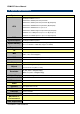
ESM-BYT User’s Manual Item Option Terminal Type VT100 VT100+ VT-UTF8 ANSI[Default] Bits per second Data Bits 9600 19200 38400 57600 115200[Default] 1[Default] 2 Parity None[Default] Even Odd Mark Space Stop Bits 1[Default] 2 Flow Control None[Default] Hardware RTS/CTS VT-UTF8 Combo Key Support Recorder Mode Resolution 100x31 Legacy OS Redirection Resolution Putty KeyPad 48 ESM-BYT User’s Manual Disabled Enabled[Default] Disabled[Default] Enabled Disabled[Default] Enabled 80x24[Default] 80x25
ESM-BYT User’s Manual Redirection After BIOS POST Always Enable[Default] BootLoader The Settings specify if BootLoader is selected then Legacy console redirection is disabled before booting to Legacy OS. Default value is Always Enable which means Legacy console redirection is enabled for Legacy OS. 3.6.2.5.
ESM-BYT User’s Manual 3.6.2.6 CPU Configuration Use the CPU configuration menu to view detailed CPU specification and configure the CPU. Item Active Processor Cores Limit CPUID Maximum Options All[Default], 1 Disabled[Default], Enabled Execute Disable Bit Disabled, Enabled[Default] Intel Virtualization Technology Disabled, Enabled[Default] Power Technology Disabled, Energy Efficient[Default] Custom 50 ESM-BYT User’s Manual Description Number of cores to enable in each processor package.
ESM-BYT User’s Manual 3.6.2.6.1 Socket 0 CPU Information 3.6.2.7 PPM Configuration Item Options CPU C state Report Disabled, Enabled[Default] Max CPU C-state C1/C6/C7[Default] Description Enable/Disable CPU C state report to OS. This option controls Max C state that the processor will support.
ESM-BYT User’s Manual 3.6.2.8 IDE Configuration Item Serial-ATA (SATA) SATA Speed Support SATA ODD Port Options Enabled[Default] Disabled, Gen1 Gen2[Default] Port0 ODD Port1 ODD No ODD[Default] SATA Mode IDE Mode AHCI Mode[Default] Serial-ATA Port 0/1 Enabled[Default] Disabled, 52 ESM-BYT User’s Manual Description Enable/Disable Serial ATA. SATA Speed Support. SATA ODD is Port0 or Port1. Select IDE/AHCI. Enable/Disable Serial ATA Port0/1.
ESM-BYT User’s Manual 3.6.2.9 Network Stack Configuration Item Network Stack Options Disabled[Default] Enabled Description Enable/Disable UEFI Network Stack. Ipv4 PXE Support Disabled Enabled[Default] Enable Ipv4 PXE Boot Support. If disabled Ipv6 PXE Support Disabled Enabled[Default] Enable Ipv6 PXE Boot Support. If disabled PXE boot wait time 0 IPV4 PXE boot option will not be created. IPV6 PXE boot option will not be created. Wait time to press ESC key to abort the PXE boot.
ESM-BYT User’s Manual 3.6.2.10 CSM Configuration Item CSM Support GateA20 Active 54 ESM-BYT User’s Manual Options Disabled, Enabled[Default] Upon Request[Default] Always Description Enable/Disable CSM Support. UPON REQUEST – GA20 can be disabled using BIOS services. ALWAYS – go not allow disabling GA20; this option is useful when any RT code is executed above 1MB.
ESM-BYT User’s Manual Option ROM Messages INT19 Trap Response Boot option filter Network Storage Video Other PCI devices Force BIOS[Default] Keep Current Set display mode for Option ROM. Immediate[Default] Postponed BIOS reaction on INT19 trapping by Option ROM: IMMEDIATE – execute the trap right away; POSTPONED – execute the traps during legacy boot.
ESM-BYT User’s Manual Disabled Enabled Disabled[Default] EHCI Hand-off Enabled[Default] Disabled 1 sec 5 sec 10 sec 20 sec[Default] 10 sec 20 sec[Default] 30 sec 40 sec USB Mass Storage Driver Support USB transfer time-out Device reset time-out Auto[Default] Manual Device power-up delay hand-off support. The XHCI ownership change should be claimed by XHCI driver. This is a workaround for OSes without EHCI hand-off support. The EHCI ownership change should be claimed by EHCI driver.
ESM-BYT User’s Manual Intel® AT Inter® AT Platform PBA TXE OVERWRITE Disabled[Default] Enabled, Disabled[Default] Enabled OVERWRITE NORMAL[Default] Enable/Disable BIOS AT Code from Running. Enable/Disable BIOS AT Code from Running. TXE OVERWRITE. NORMAL: OverWrite Pin as high. (TXE enabled) OVERWRITE: OverWrite Pin as low. (TXE disabled). 3.6.2.
ESM-BYT User’s Manual 3.6.3 Chipset 3.6.3.1 North Bridge Item Max TOLUD 58 ESM-BYT User’s Manual Option Dynamic[Default] 2 GB 2.25 GB 2.5 GB 2.75 GB 3 GB Description Maximum Value of TOLUD.
ESM-BYT User’s Manual 3.6.3.1.
ESM-BYT User’s Manual 3.6.3.1.
ESM-BYT User’s Manual 2k 3k 5k 10k 20k 3.6.3.2 South Bridge Item High Precision Timer Option Disabled Enabled[Default] Description Enable or Disable the High Precision Event Timer. 3.6.3.2.
ESM-BYT User’s Manual Item Option Audio Controller Enabled[Default], Disabled HDMI Port C Enabled[Default], Disabled Description Control Detection of the Azalia device. Disabled = Azalia will be unconditionally disabled. Enabled = Azalia will be unconditionally Enabled. Auto = Azalia will be enabled if present disabled otherwise. Enable/Disable HDMI Port C. 3.6.3.2.2 USB Configuration Item Option OS Selection Windows 8.
ESM-BYT User’s Manual 3.6.3.2.3 PCI Express Configuration Item PCI Express Port 0/1/2/3 Speed 3.6.4 Option Enabled[Default], Disabled Auto[Default] Gen 2 Gen 1 Description Enable or Disable the PCI Express Port 0/1/2/3 in the Chipset. Configure PCIe Port Speed.
ESM-BYT User’s Manual Administrator Password Set setup Administrator Password User Password Set User Password 3.6.4.1 Secure Boot menu Item Option Secure Boot Disabled Enabled[Default] Secure Boot Mode Standard[Default] Custom 64 ESM-BYT User’s Manual Description Secure Boot can be enabled if 1.System running in User mode with enrolled Platform Key(PK) 2.CSM function is disabled. Secure Boot mode selector.
ESM-BYT User’s Manual 3.6.5 Boot Item Option Setup Prompt Timeout 1~ 65535 Bootup NumLock State Quiet Boot On[Default] Off Disabled[Default] Enabled Fast Boot Disabled[Default] Enabled Boot Option Priorities Depends on device plugged. Description Number of seconds to wait for setup activation key. 65535(0xFFFF) means indefinite waiting.
ESM-BYT User’s Manual 3.6.6 Save and exit 3.6.6.1 Save Changes and Reset Reset the system after saving the changes. 3.6.6.2 Discard Changes and Reset Any changes made to BIOS settings during this session of the BIOS setup program are discarded. The setup program then exits and reboots the controller. 3.6.6.3 Restore Defaults This option restores all BIOS settings to the factory default.
ESM-BYT User’s Manual 4. Drivers Installation Note: Installation procedures and screen shots in this section are for your reference and may not be exactly the same as shown on your screen.
ESM-BYT User’s Manual 4.1 Install Chipset Driver Insert the Supporting DVD-ROM to DVD-ROM drive, and it should show the index page of Avalue’s products automatically. If not, locate Index.htm and choose the product from the menu left, or link to \Driver_Chipset\Intel\ESM-BYT. Note: The installation procedures and screen shots in this section are based on Windows 7 operation system. If the warning message appears while the installation process, click Continue to go on. Step 3. Click Install. Step 4.
ESM-BYT User’s Manual 4.2 Install Display Driver Insert the Supporting DVD-ROM to DVD-ROM drive, and it should show the index page of Avalue’s products automatically. If not, locate Index.htm and choose the product from the menu left, or link to \VGA\ESM-BYT. Note: The installation procedures and screen shots in this section are based on Windows 7 operation system. Step 1. Click Next to continue installation. Step 3. Click Next. Step 4. Click Next. Step 5. Click Finish to complete setup. Step 2.
ESM-BYT User’s Manual 4.3 Install LAN Driver (For Intel I211AT) Insert the Supporting DVD-ROM to DVD-ROM drive, and it should show the index page of Avalue’s products automatically. If not, locate Index.htm and choose the product from the menu left, or link to \Driver_Gigabit\Intel\I211AT\ESM-BYT_LAN. Note: The installation procedures and screen shots in this section are based on Windows 7 operation system. Step 3. Click Next. Step 4. Click Install. Step 1. Click Next to continue installation. Step 2.
ESM-BYT User’s Manual Step 6. Click Finish to complete setup.
ESM-BYT User’s Manual 4.4 Install USB 3.0 Driver Insert the Supporting DVD-ROM to DVD-ROM drive, and it should show the index page of Avalue’s products automatically. If not, locate Index.htm and choose the product from the menu left, or link to \Utility\ESM-BYT_USB3.0. Note: The installation procedures and screen shots in this section are based on Windows 7 operation system. If the warning message appears while the installation process, click Continue to go on. Step 3.
ESM-BYT User’s Manual 4.5 Install Audio Driver Insert the Supporting DVD-ROM to DVD-ROM drive, and it should show the index page of Avalue’s products automatically. If not, locate Index.htm and choose the product from the menu left, or link to \Driver_Audio\Realtek\ALC892\ESM-BYT_Audio. Note: The installation procedures and screen shots in this section are based on Windows 7 operation system. If the warning message appears while the installation process, click Continue to go on. Step 3.
ESM-BYT User’s Manual 5.
ESM-BYT User’s Manual Unit: mm ESM-BYT User’s Manual 75
ESM-BYT User’s Manual Unit: mm 76 ESM-BYT User’s Manual