ESM-LX800 AMD Geode LX800 ETX Module Quick Installation Guide 1st Ed – 13 April 2009 Part No.
ESM-LX800 FCC Statement THIS DEVICE COMPLIES WITH PART 15 FCC RULES. OPERATION IS SUBJECT TO THE FOLLOWING TWO CONDITIONS: (1) THIS DEVICE MAY NOT CAUSE HARMFUL INTERFERENCE. (2) THIS DEVICE MUST ACCEPT ANY INTERFERENCE RECEIVED INCLUDING INTERFERENCE THAT MAY CAUSE UNDESIRED OPERATION. THIS EQUIPMENT HAS BEEN TESTED AND FOUND TO COMPLY WITH THE LIMITS FOR A CLASS "A" DIGITAL DEVICE, PURSUANT TO PART 15 OF THE FCC RULES.
Quick Installation Guide Disclaimer Avalue Technology Inc. reserves the right to make changes, without notice, to any product, including circuits and/or software described or contained in this manual in order to improve design and/or performance.
ESM-LX800 Contents 1. Getting Started............................................................................................................5 1.1 Safety Precautions ................................................................................................5 1.2 Packing List ...........................................................................................................5 2. Hardware Configuration..........................................................................................
Quick Installation Guide 1. Getting Started 1.1 Safety Precautions Warning! Always completely disconnect the power cord from your chassis whenever you work with the hardware. Do not make connections while the power is on. Sensitive electronic components can be damaged by sudden power surges. Only experienced electronics personnel should open the PC chassis. Caution! Always ground yourself to remove any static charge before touching the CPU card.
ESM-LX800 2.
Quick Installation Guide 2.
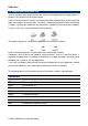
ESM-LX800 2.2 Jumper and Connector List You can configure your board to match the needs of your application by setting jumpers. A jumper is the simplest kind of electric switch. It consists of two metal pins and a small metal clip (often protected by a plastic cover) that slides over the pins to connect them. To “close” a jumper you connect the pins with the clip. To “open” a jumper you remove the clip. Sometimes a jumper will have three pins, labeled 1, 2, and 3.
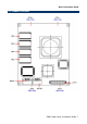
Quick Installation Guide 2.3 Setting Jumpers & Connectors 2.3.
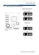
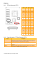
ESM-LX800 2.3.2 TFT Panel Connector (JTFT1) 2.3.2.1 Signal PIN PIN Signal +5V 2 1 +5V GND 4 3 GND +3.3V 6 5 +3.
Quick Installation Guide 2.3.2.
ESM-LX800 12 ESM-LX800 Quick Installation Guide