FPC-05R1 5.7” SVGA TFT RISC Multifunctional Panel PC Quick Reference Guide 1st Ed –25 July 2013 Copyright Notice Copyright 2013 Avalue Technology Inc., ALL RIGHTS RESERVED. Part No.
FPC-05R1 CONTENT 1. Getting Started ............................................................................................................ 3 1.1 1.2 1.3 1.4 2. 1.4.1 Front & Top View ......................................................................................................................... 6 1.4.2 Right Side View ............................................................................................................................ 6 1.4.3 Left Side View ....................
Quick Reference Guide 1. Getting Started 1.1 Safety Precautions Warning! Always completely disconnect the power cord from your chassis whenever you work with the hardware. Do not make connections while the power is on. Sensitive electronic components can be damaged by sudden power surges. Only experienced electronics personnel should open the PC chassis. Caution! Always ground yourself to remove any static charge before touching the CPU card.
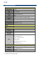
FPC-05R1 1.3 System Specifications System Mother Board RSC-IMX51 CPU Freescale i.MX51 800 MHz PMU Freescale MC13892 eMMC Memory RTC Watchdog Timer Adapter 4GB onboard 512MB DDR2 SDRAM onboard ISL1208 Generates a time-out system reset, setting via software +12 Vdc / 2 A (24W) Power Management Support AT Mode Expansion Card Operating System Other SD socket Support SDHC (eSDHC-2) Linux & Win CE 6.
Quick Reference Guide Switch Expansion Slots Others 1 x On/Off Power Switch 1 x SD socket Support SDHC (eSDHC-2) 1 x Reset button Mechanical Power Type Power Connector Type Color Fanless Mounting AT, +12 Vdc / 2 A (24W) DC Power Jack Front & Rear panel Black Yes Wall/Stand/VESA 100 mm X 100 mm Dimension TBD Weight TBD Reliability EMI Test CE/FCC Class A Vibration Test As standards Drop Test As standards Operating Temperature 0°C to 40°C (32°F to 140°F) Operating Humidity 0%~90% relative humi
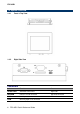
FPC-05R1 1.4 System Overview 1.4.1 Front & Top View 1.4.
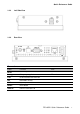
Quick Reference Guide 1.4.3 Left Side View 1.4.4 Rear View Connectors Label Function DC-IN +12V DC power-in connector Debug port Debug target application LAN RJ-45 Fast Ethernet connector DIP Boot Mode selector PWR System power switch RESET Reset button USB1&2 USB 2.
FPC-05R1 2. Hardware Configuration Jumper and Connector Setting For advanced information, please refer to: 1- RSC-IMX51 Installation Guide or User’s Manual 2- AUX-MPCIE (Optional) Installation Guide. Note: If you need more information, please visit our website: http://www.avalue.com.
Quick Reference Guide 2.1 Jumper & connector list Connectors Label Function Note COM Serial port connector DB-9 male connector DC-IN +12V DC power-in connector Debug port Debug target application LAN RJ-45 Fast Ethernet connector DIP Boot Mode selector MINI USB USB on The Go connector PWR System power switch RESET Reset button SD Card Slot SD/SDHC card socket USB1&2 USB 2.
FPC-05R1 2.2 Jumper & connector settings 2.2.
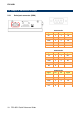
Quick Reference Guide 2.2.2 Boot Mode selector (DIP) Boot from onboard SD Boot from SD socket Signal PIN PIN BMOD1 1 5 BMOD0 2 6 BT_SRC[1] 3 7 BT_SRC[0] 4 8 Signal +V2D775_BOOT +V1D8_DIG1 DIP ON ↓ USB OTG mode DIP ON ↓ Please note: DIP Switch setting: 0=Off, 1=On When Position4 is switched On, the system is forced to power On as soon as power is applied. Switch to Off mode for normal operation. 2.2.
FPC-05R1 2.2.