FPC 17”/18W”/21W” Series 17” / 18”W / 21”W TFT Touch Panel PC Quick Reference Guide 1st Ed –02 September 2013 Copyright Notice Copyright 2013 Avalue Technology Inc., ALL RIGHTS RESERVED. Part No.
FPC 17”/18W”/21W” Series 1. Getting Started 1.1 Safety Precautions Warning! Always completely disconnect the power cord from your chassis whenever you work with the hardware. Do not make connections while the power is on. Sensitive electronic components can be damaged by sudden power surges. Only experienced electronics personnel should open the PC chassis. Caution! Always ground yourself to remove any static charge before touching the CPU card.
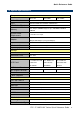
Quick Reference Guide 1.3 System Specifications Component FPC-1707 FPC-18W07 FPC-21W07 Mother Board EMX-CDV CPU Onboard Intel® Atom™ D2550 1.86GHz CPU CPU Cooler (Type) Fanless Heatsink Memory System Power Requirements Adapter Two 204-pin SODIMM Supports Up to 4GB DDR3 1066MHz SDRAM +12V DC Power Input Input: 100 ~ 250Vdc/ 47 ~ 63Hz Output: 60W Adapter (12V @ 5A Adapter) Speaker 8Ω 2W*2 Wireless LAN optional USB WiFi 802.
FPC 17”/18W”/21W” Series Dimension 387.5mm x 346mm 459.5mm x 309mm 526mm x 346.5mm x 76.6mm x 79.6mm x 80.4mm Weight 6.14Kgs 5.77Kgs 7.
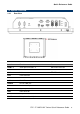
Quick Reference Guide 1.4 System Overview 1.4.
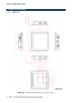
FPC 17”/18W”/21W” Series 1.5 System Dimensions 1.5.1 FPC-1707 (Unit: mm) Warning: Use suitable mounting apparatus to avoid risk of injury.
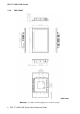
Quick Reference Guide 1.5.2 FPC-18W07 (Unit: mm) Warning: Use suitable mounting apparatus to avoid risk of injury.
FPC 17”/18W”/21W” Series 1.5.3 FPC-21W07 (Unit: mm) Warning: Use suitable mounting apparatus to avoid risk of injury.
Quick Reference Guide 2. Hardware Configuration For advanced information, please refer to: 1- FPC 17”/18W”/21W” Series Quick Reference Guide or User’s Manual Note: If you need more information, please visit our website: http://www.avalue.com.
FPC 17”/18W”/21W” Series 2.1 FPC 17”/18W”/21W” Series connector mapping 2.1.
Quick Reference Guide 2.2 Installing Hard Disk & Memory WARNING: Make sure the power is completely cut off before opening the device. Remove 12 screws as indicated below to open the back of the chassis. 2.2.1 Install Memory Step 1. Insert the SODIMM into the memory socket.
FPC 17”/18W”/21W” Series 2.2.2 Install HDD Step 1. Attach the HDD bracket to the 2.5” SATA HDD by means of 4 screws as shown above, and then connect HDD data and power cables. Step 2. Position the HDD bracket & 2.5” SATA HDD assembly into the chassis and lock with 4 screws as indicated above.