LPC-1009/1209/1509/ 1709/1909 Series Fanless Multifunctional Touch Panel Computer Quick Reference Guide 1st Ed – 11 November 2014 Copyright Notice Copyright 2014 Avalue Technology Inc., ALL RIGHTS RESERVED. Part No.
LPC-1009/1209/1509/1709/1909 Series FCC Statement THIS DEVICE COMPLIES WITH PART 15 FCC RULES. OPERATION IS SUBJECT TO THE FOLLOWING TWO CONDITIONS: (1) THIS DEVICE MAY NOT CAUSE HARMFUL INTERFERENCE. (2) THIS DEVICE MUST ACCEPT ANY INTERFERENCE RECEIVED INCLUDING INTERFERENCE THAT MAY CAUSE UNDESIRED OPERATION. THIS EQUIPMENT HAS BEEN TESTED AND FOUND TO COMPLY WITH THE LIMITS FOR A CLASS "A" DIGITAL DEVICE, PURSUANT TO PART 15 OF THE FCC RULES.
Quick Reference Guide these products are free from patent, copyright, or mask work right infringement, unless otherwise specified. Applications that are described in this manual are for illustration purposes only. Avalue Technology Inc. makes no representation or warranty that such application will be suitable for the specified use without further testing or modification.
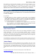
LPC-1009/1209/1509/1709/1909 Series Content 1. Getting Started ........................................................................................................ 5 1.1 1.2 1.3 1.4 Safety Precautions .................................................................................................... 5 Packing List ............................................................................................................... 5 System Specifications ....................................................
Quick Reference Guide 1. Getting Started 1.1 Safety Precautions Warning! Always completely disconnect the power cord from your chassis whenever you work with the hardware. Do not make connections while the power is on. Sensitive electronic components can be damaged by sudden power surges. Only experienced electronics personnel should open the PC chassis. Caution! Always ground yourself to remove any static charge before touching the CPU card.
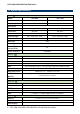
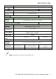
LPC-1009/1209/1509/1709/1909 Series 1.3 System Specifications Panel LPC-1009 LPC-1209 LCD size 10.4", 4:3 12.1", 4:3 Display type XGA TFT XGA Model Resolution 1024 x 768 Pixel pitch 0.0685mm(H) x 0.2055mm(V) 0.240mm(H) x 0.
Quick Reference Guide Audio AC97 Codec Realtek ALC892 supports 5.1-CH Audio Audio Interface Connector: Line out Ethernet LAN Chip Dual Intel I210IT PCI-E Gigabit LAN Ethernet Interface 10/100/1000 Base-Tx Fast Ethernet compatible Mechanical & Environment Color Mounting Front Silver & Rear panel Black Wall/Stand/VESA 75 mm x 75 mm System Power +12 V ~ +26 V Requirement Input: 100~240 Vac/ 50~60 Hz Power Adapter Output: +12 Vdc / 5 A (60W) Power Type Operating Temp.
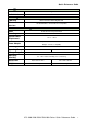
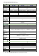
LPC-1009/1209/1509/1709/1909 Series Panel Model LCD size Display type LPC-1509 LPC-1709 LPC-1909 15", 4:3 17", 4:3 19", 4:3 XGA SXGA Resolution 1024 x 768 1280 x 1024 Pixel pitch 0.297mm(H) x 0.297mm(V) Luminance 400 cd/m² 0.264mm(H) x 0.264mm(V) 0.294mm (H) x 0.
Quick Reference Guide Resolution HDMI 1.4a resolutions up to 1920x1200@ 60 24bpp Dual Display LVDS + HDMI Audio AC97 Codec Realtek ALC892 supports 5.
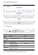
LPC-1009/1209/1509/1709/1909 Series 1.4 System Overview 1.4.1 Top View LPC-1009/1209 LPC-1509/1709 LPC-1909 1.4.2 Bottom View Connectors Label Function POWER Power on button Compact Flash/COM2 CF Type I/II Socket with Ejector Optional for 2nd COM port COM1 Serial port 1 connector DB-9 male connector LINE OUT Line-out audio jack USB 1 x USB 2.0 connector 1 x USB 3.
Quick Reference Guide PWR System power indicator VGA/HDMI HDMI connector RESET Reset button DC-IN DC Power-in connector LPC-1009/1209/1509/1709/1909 Series Quick Reference Guide 11
LPC-1009/1209/1509/1709/1909 Series 1.5 System Dimensions 1.5.
Quick Reference Guide 1.5.
LPC-1009/1209/1509/1709/1909 Series 1.5.
Quick Reference Guide 1.5.
LPC-1009/1209/1509/1709/1909 Series 1.5.
Quick Reference Guide 2. Hardware Configuration For advanced information, please refer to: 1- EBM-BYT User’s Manual Note: If you need more information, please visit our website: http://www.avalue.com.
LPC-1009/1209/1509/1709/1909 Series 2.1 LPC-1009/1209/1509/1709/1909 Series connector mapping 2.1.
Quick Reference Guide 2.1.
LPC-1009/1209/1509/1709/1909 Series 2.2 Installing Hard Disk & Memory (For LPC-1009/1209) Step 1. Unfasten 6 screws from the case. Then take off the top chassis. Step 2. Insert the SODIMM into the memory socket.
Quick Reference Guide SATA connector 1 Step 3-1. SATA HDD Installation: By default, the SATA cables had been inserted to the according connectors. Just connect to SATA HDD with the two cables. HDD Step 3-2. Insert the HDD into the Drive Bay. Remember to place the HDD down to the bottom exactly in order to screw the device tightly. Step 4. Place back the chassis with 6 screws locked.
LPC-1009/1209/1509/1709/1909 Series 2.3 Installing Hard Disk & Memory (For LPC-1509/1709/1909) Step 1. Memory Installation: Unfasten 6 screws from the case to take off the top chassis. Step 2. Insert the SODIMM into the memory socket. Step 3-1. HDD Installation: Unfasten 2 screws of the HDD bracket and take it off.
Quick Reference Guide Step 3-2. Insert the HDD into the bracket and fasten 4 screws. SATA connector 1 Step 3-3. SATA HDD Installation: By default, the SATA cables had been inserted to the according connectors. Just connect to SATA HDD with the two cables.
LPC-1009/1209/1509/1709/1909 Series HDD Step 3-4. Insert the HDD back and fasten 2 screws. Step 4. Place back the chassis with 6 screws locked.