REV-SA01 SMARC Evaluation Carrier Board User’s Manual 2nd Ed – 16 October 2014 Part No.
REV-SA01 User’s Manual Content 1. Getting Started ............................................................................................................ 4 1.1 Safety Precautions .................................................................................................... 4 1.2 Packing List ............................................................................................................... 4 1.3 Document Amendment History ..............................................................
REV-SA01 User’s Manual 3.10 Set up for building Android image file...................................................................... 38 3.11 Building up Andrioid image file ................................................................................ 39 3.12 Use MfgTool to flash Android into onboard eMMC..................................................
REV-SA01 User’s Manual 1. Getting Started 1.1 Safety Precautions Warning! Always completely disconnect the power cord from your chassis whenever you work with the hardware. Do not make connections while the power is on. Sensitive electronic components can be damaged by sudden power surges. Only experienced electronics personnel should open the PC chassis. Caution! Always ground yourself to remove any static charge before touching the CPU card.
REV-SA01 User’s Manual 1.
REV-SA01 User’s Manual 1.4 Manual Objectives This manual describes in details Avalue Technology REV-SA01 Single Board. We have tried to include as much information as possible but we have not duplicated information that is provided in the standard IBM Technical References, unless it proved to be necessary to aid in the understanding of this board. We strongly recommend that you study this manual carefully before attempting to set up REV-SA01 series or change the standard configurations.
REV-SA01 User’s Manual 1.5 System Specifications System SMARC CPU Module socket: Accepts 82mm x 50mm SMARC Modules DB9 x 1 DB15 x 1 HDMI x 1 Edge conn Mini-USB x 1 USB Type A x 2 RJ45 x 2 SD Socket x 1 Backlight conn 5V, GND, ENBKL, VR, PWM LVDS connector Hirose DF13-40DS-1.
REV-SA01 User’s Manual 1.6 Architecture Overview—Block Diagram The following block diagram shows the architecture and main components of REV-SA01.
REV-SA01 User’s Manual 2.
REV-SA01 User’s Manual 2.
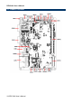
REV-SA01 User’s Manual REV-SA01 User’s Manual 11
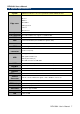
REV-SA01 User’s Manual 2.2 Jumper and Connector List You can configure your board to match the needs of your application by setting jumpers. A jumper is the simplest kind of electric switch. It consists of two metal pins and a small metal clip (often protected by a plastic cover) that slides over the pins to connect them. To “close” a jumper you connect the pins with the clip. To “open” a jumper you remove the clip. Sometimes a jumper will have three pins, labeled 1, 2, and 3.
REV-SA01 User’s Manual AMPLIFIER connector JAMP1 4 x 1 wafer, pitch 2.00mm JMIC1 Line In, MIC connector 4 x 1 wafer, pitch 2.00mm LAN1 RJ-45 Ethernet connector VGA1 VGA connector LED3 LED connector MINIUSB1 Mini USB connector for Boot/Debug COM1 Serial Port 1 connector JCOM2 Serial Port 2 connector 2 x 6 wafer, pitch 2.00mm HDMI1 HDMI connector HDMI_19P JLVDS1 LVDS Interface connector 20 x 2 wafer, pitch 1.25mm PWR1 Power connector 2 x 2 wafer, pitch 4.
REV-SA01 User’s Manual 2.3 Setting Jumpers & Connectors 2.3.
REV-SA01 User’s Manual 2.3.2 General purpose I/O Power selector (JDIOP1) +5V +3.3V 2.3.
REV-SA01 User’s Manual 2.3.4 Battery connector 2 (JBAT2) Signal PIN PIN Signal +V_BATTERY 1 2 +V_BATTERY +V_BATTERY 3 4 GND GND 5 6 BAT_DATA BAT_TS 7 8 BAT_CLK GND 9 10 GND 2.3.
REV-SA01 User’s Manual 2.3.6 SATA Power connector (JSPWR1) Signal PIN GND 1 +5V 2 2.3.
REV-SA01 User’s Manual 2.3.8 LVDS Interface connector (JLVDS1) Signal 18 REV-SA01 User’s Manual PIN PIN Signal +5V 2 1 +3.3V +5V 4 3 +3.
REV-SA01 User’s Manual 2.3.9 Can Bus connector 1 (JCAN1) Signal PIN CAN0_H 1 GND 2 CAN0_L 3 GND 4 Signal PIN CAN1_H 1 GND 2 CAN1_L 3 GND 4 2.3.
REV-SA01 User’s Manual 2.3.11 LCD inverter connector (JBKL1) Signal PIN NC 1 GND 2 LCD_BKLT_EN 3 LCD_BKLT_PWM 4 +5V 5 2.3.
REV-SA01 User’s Manual 2.3.13 USB connector (JUSB1) Signal PIN +4V 1 USB3_D- 2 USB3_D+ 3 GND 4 GND 5 2.3.
REV-SA01 User’s Manual 2.3.
REV-SA01 User’s Manual 3.
REV-SA01 User’s Manual 3.1 Download Source code for building Ubuntu image file Please make a folder for storing the source code first then typing the command below to get started for the source code download. $ Sudo apt-get install git $ git clone guest@202.55.227.57:freescale/core.git -b SMARC About password, please check with Avalue Sales or PM to get it. 3.2 Set up a Linux host for building U-boot & Kernel Image We support to compile u-boot & Kernel on Ubuntu 12.
REV-SA01 User’s Manual 3. You can find the u-boot(u-boot.bin) & Kernel(uImage) under folder ”core” as below after the compiling is finish. PS: If you would like to use Mfgtool for flashing image file, you must put the file u-boot.bin and uImage under “~\Image\smarc” for right detected path.
REV-SA01 User’s Manual 3.4 Use MfgTool to flash Ubuntu into onboard eMMC Manufacturing tool, a successor of ATK, provides a series of new features to power your mass production work. The features like windows style GUI, multiple devices support, explicit status monitoring, versatile functionalities and highly flexible architecture make it a best choice to meet your critical timing, cost and customization requirements.
REV-SA01 User’s Manual 5. Select the MCU option by name, if the MCU of module board is “i.MX6 Solo”, please click “MX6DL Linux Update”, and click “Linux-ubuntu” (Ubuntu GUI version) for the OS of flashing, then click “Run MFG Tool”. Or the if the MCU of module board is “i.MX6 Quad core”, please click “MX6Q Linux Update”, and click “Linux-ubuntu” (Ubuntu GUI version) for the OS of flashing, then click “Run MFG Tool”. 6.
REV-SA01 User’s Manual 7. Click “Start” to flash image file. 8. It will show “Done” after flashing is finish, then click “Stop” and “Exit” to close the screen. 9. You can also get the information from Terminal (debug portCOM1) after flashing is finish.
REV-SA01 User’s Manual 3.5 Create a bootable SD card with Ubuntu 12.04 file system Please insert a SD card in the card reader on your Linux host PC 1) Check device node of your SD card by command below.
REV-SA01 User’s Manual $ sudo umount /dev/sdd1 $ sudo mount /dev/sdd1 /mnt $ cd /mnt $ sudo tar jxvpf ~/ubuntu.tar.bz2 $ cd $ sudo umount /dev/sdd1 The Ubuntu file system content is now on the SD card. You can insert it to mainboard then turn on the DIP switch pin2&3 as below for booting.
REV-SA01 User’s Manual 3.6 Bootloader settings for booting from SD card 1) Please turn on the Pin 2&3 of the DIP switch as below for booting from SD card . 2) 3) 4) 5) Insert SD card on SD socket. Connect RS232 cross over cable from COM1 of mianboard to COM port of Host PC. Run hyper terminal program on Host PC (teraterm on Windows or minicom on Linux) Power on mainboard and press ”space” key to get into bootloader menu.
REV-SA01 User’s Manual 6) Set boot device as below SMARC U-Boot >setenv linux_cmd ‘setenv bootargs ${linux_bootargs};mmc dev 1;mmc read ${loadaddr} 0x800 0x3000;bootm’ SMARC U-Boot > setenv linux_bootargs 'console=tty0 console=ttymxc0,115200 root=/dev/mmcblk1p1 rootwait rw' SMARC U-Boot> saveenv SMARC U-Boot> boot 32 REV-SA01 User’s Manual
REV-SA01 User’s Manual 3.7 Bootloader settings for booting from onboard eMMC 1) Please turn on the Pin 1 of the DIP switch as below for booting from onboard eMMC. 2) 3) 4) Insert SD card on SD socket. Connect RS232 cross over cable from COM1 of mianboard to COM port of Host PC. Run hyper terminal program on Host PC (teraterm on Windows or minicom on Linux) Power on mainboard and press ”space” key to get into bootloader menu.
REV-SA01 User’s Manual SMARC U-Boot > setenv linux_bootargs 'console=tty0 console=ttymxc0,115200 root=/dev/mmcblk0p1 rootwait rw' SMARC U-Boot> saveenv SMARC U-Boot> boot 34 REV-SA01 User’s Manual
REV-SA01 User’s Manual 3.8 Display output application of IMX6 This section describes how to setup the display output for LVDS, HDMI, VGA of IMX6 module. 1. You can find the file of resolution setup of LVDS&VGA under the directory ”..~/core/kernel/drivers/video/mxc”, for LVDS is ”ldb.c”, and for VGA is ” mxc_lcdif.c”. ”ldb.c” ”mxc_lcdif.c” 2. You need to fill the resolution parameter(.mode_str) on the file ”rev_sa01.
REV-SA01 User’s Manual 3. Finally, you should fill the parameter for booting on the file ”mx6_smarc.h” under the directory ”~/core/u-boot/include/configs/”. Please add ”video=mxcfb0:dev=display name” on the column 132 "rootwait rw \0" to enable display output function when booting. 4. Please refer ch1.3 to re-build the u-boot &Kernel binary file for booting. Note: If you need to use double display output in Ubuntu, you should setup the ” rev_sa01.
REV-SA01 User’s Manual video=mxcfb1:dev=second display neme” to mx6_smarc.h, but for this application, you also need to write a program for controling the second diplay first or the second display will not enable after you follow up all the setting above.
REV-SA01 User’s Manual 3.9 Download Android Source Code for building image file Please make a folder for storing the source code first then typing the command below to get started for the source code download. $ sudo apt-get install git $ git clone guest@202.55.227.57:freescale/imx6/Android.git -b 4.4.2-SMARC About password, please check with Avalue Sales or PM to get it. 3.10 Set up for building Android image file We support to compile u-boot & Kernel on Ubuntu 12.
REV-SA01 User’s Manual 3.11 Building up Andrioid image file You can follow up the steps below to compile Android image file after download the source code. 1. Please move to the folder ”Android” then start to compile image file. 2. Type the command to compile image file. $ ./run.sh –j16 (-j number means multi jobs for more efficiant building, you can add it according to your CPU performance of PC, e.g. mine is ”–j16” as below ). 3. You can find the finished image file(u-boot-6q.bin, u-boot-6solo.
REV-SA01 User’s Manual PS: If you would like to use Mfgtool for flashing image file, you must put all the files u-boot-6q.bin, u-boot-6solo.bin, system.img, recover.img, boot.img under “~\Image\smarc\android” for right detected path.
REV-SA01 User’s Manual 3.12 Use MfgTool to flash Android into onboard eMMC Manufacturing tool, a successor of ATK, provides a series of new features to power your mass production work. The features like windows style GUI, multiple devices support, explicit status monitoring, versatile functionalities and highly flexible architecture make it a best choice to meet your critical timing, cost and customization requirements.
REV-SA01 User’s Manual 4) Click “MfgTool2.exe” to flash image file into smarc module. 5) Click “Start” to flash image file. 6) It will show “Done” after flashing is finish, then click “Stop” and “Exit” to close the screen.
REV-SA01 User’s Manual 7) You can also get the information from Terminal (debug portCOM1) after flashing is finish.