REV-SA01 SMARC Evaluation Carrier Board Quick Installation Guide 1st Ed – 11 December 2013 Part No.
REV-SA01 Quick Installation Guide Content 1. Getting Started ............................................................................................................ 3 1.1 Safety Precautions .................................................................................................... 3 1.2 Packing List ............................................................................................................... 3 2. Hardware Configuration ........................................................
Quick Installation Guide 1. Getting Started 1.1 Safety Precautions Warning! Always completely disconnect the power cord from your chassis whenever you work with the hardware. Do not make connections while the power is on. Sensitive electronic components can be damaged by sudden power surges. Only experienced electronics personnel should open the PC chassis. Caution! Always ground yourself to remove any static charge before touching the CPU card.
REV-SA01 Quick Installation Guide 2.
Quick Installation Guide 2.
REV-SA01 Quick Installation Guide 6 REV-SA01 Quick Installation Guide
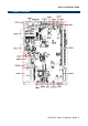
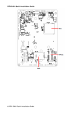
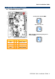
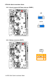
Quick Installation Guide 2.2 Jumper and Connector List You can configure your board to match the needs of your application by setting jumpers. A jumper is the simplest kind of electric switch. It consists of two metal pins and a small metal clip (often protected by a plastic cover) that slides over the pins to connect them. To “close” a jumper you connect the pins with the clip. To “open” a jumper you remove the clip. Sometimes a jumper will have three pins, labeled 1, 2, and 3.
REV-SA01 Quick Installation Guide Line In, MIC connector JMIC1 4 x 1 wafer, pitch 2.00mm LAN1 RJ-45 Ethernet connector VGA1 VGA connector LED3 LED connector MINIUSB1 Mini USB connector for Boot/Debug COM1 Serial Port 1 connector JCOM2 Serial Port 2 connector 2 x 6 wafer, pitch 2.00mm HDMI1 HDMI connector HDMI_19P JLVDS1 LVDS Interface connector 20 x 2 wafer, pitch 1.25mm PWR1 Power connector 2 x 2 wafer, pitch 4.20mm USB1 USB connector JUSB1 USB connector 5 x 1 wafer, pitch 2.
Quick Installation Guide 2.3 Setting Jumpers & Connectors 2.3.
REV-SA01 Quick Installation Guide 2.3.2 General purpose I/O Power selector (JDIOP1) +5V +3.3V 2.3.
Quick Installation Guide 2.3.4 General purpose I/O connector (JDIO1) Signal PIN PIN Signal DIO_GP10 1 2 DIO_GP20 DIO_GP11 3 4 DIO_GP21 DIO_GP12 5 6 DIO_GP22 DIO_GP13 7 8 DIO_GP23 SMB_DATA_9555 9 10 SMB_CLK_9555 +VDIO 11 12 GND 2.3.
REV-SA01 Quick Installation Guide 2.3.6 LVDS Interface connector (JLVDS1) Signal 12 REV-SA01 Quick Installation Guide PIN PIN Signal +5V 2 1 +3.3V +5V 4 3 +3.
Quick Installation Guide 2.3.7 Can Bus connector 1 (JCAN1) Signal PIN CAN0_H 1 GND 2 CAN0_L 3 GND 4 Signal PIN CAN1_H 1 GND 2 CAN1_L 3 GND 4 2.3.
REV-SA01 Quick Installation Guide 2.3.9 LCD inverter connector (JBKL1) Signal PIN NC 1 GND 2 LCD_BKLT_EN 3 LCD_BKLT_PWM 4 +5V 5 2.3.
Quick Installation Guide 2.3.11 Line In, MIC connector (JMIC1) Signal PIN MICIN_DET 1 MIC_RAW 2 MICBIAS2_RAW 3 GND 4 2.3.
REV-SA01 Quick Installation Guide 2.3.13 Power connector (PWR1) Signal PIN PIN Signal RVSP_G 1 2 RVSP_G +VIN 3 4 +VIN 2.3.