SEAX-H81 Intel® H81 Express Chipset ATX Motherboard User’s Manual 1st Ed – 11 August 2014 Part No.
SEAX-H81 User’s Manual FCC Statement THIS DEVICE COMPLIES WITH PART 15 FCC RULES. OPERATION IS SUBJECT TO THE FOLLOWING TWO CONDITIONS: (1) THIS DEVICE MAY NOT CAUSE HARMFUL INTERFERENCE. (2) THIS DEVICE MUST ACCEPT ANY INTERFERENCE RECEIVED INCLUDING INTERFERENCE THAT MAY CAUSE UNDESIRED OPERATION. THIS EQUIPMENT HAS BEEN TESTED AND FOUND TO COMPLY WITH THE LIMITS FOR A CLASS "A" DIGITAL DEVICE, PURSUANT TO PART 15 OF THE FCC RULES.
SEAX-H81 User’s Manual otherwise specified. Applications that are described in this manual are for illustration purposes only. Avalue Technology Inc. makes no representation or warranty that such application will be suitable for the specified use without further testing or modification. Life Support Policy Avalue Technology’s PRODUCTS ARE NOT FOR USE AS CRITICAL COMPONENTS IN LIFE SUPPORT DEVICES OR SYSTEMS WITHOUT THE PRIOR WRITTEN APPROVAL OF Avalue Technology Inc. As used herein: 1.
SEAX-H81 User’s Manual Content 1. Getting Started ............................................................................................................ 6 1.1 Safety Precautions .......................................................................................... 6 1.2 Packing List .................................................................................................... 6 1.3 Document Amendment History....................................................................... 7 1.
SEAX-H81 User’s Manual 3.6.1 Main Menu ............................................................................................ 30 3.6.1.1 System Language .......................................................................... 30 3.6.1.2 System Date .................................................................................. 30 3.6.1.3 System Time .................................................................................. 30 3.6.2 Advanced BIOS settings ..................................
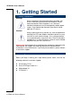
SEAX-H81 User’s Manual 1. Getting Started 1.1 Safety Precautions Warning! Always completely disconnect the power cord from your chassis whenever you work with the hardware. Do not make connections while the power is on. Sensitive electronic components can be damaged by sudden power surges. Only experienced electronics personnel should open the PC chassis. Caution! Always ground yourself to remove any static charge before touching the CPU card.
SEAX-H81 User’s Manual 1.
SEAX-H81 User’s Manual 1.4 Manual Objectives This manual describes in details Avalue Technology SEAX-H81 Single Board. We have tried to include as much information as possible but we have not duplicated information that is provided in the standard IBM Technical References, unless it proved to be necessary to aid in the understanding of this board. We strongly recommend that you study this manual carefully before attempting to set up SEAX-H81 series or change the standard configurations.
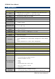
SEAX-H81 User’s Manual 1.5 Specifications System CPU BIOS Pentium® and Celeron® Processors (Max. TDP at 84W) System Chipset I/O Chip th Intel® LGA1150 Socket Supports 4 Generation Core™ Refresh i7/ i5/ i3, AMI uEFI BIOS, 64Mbit SPI Flash ROM Intel® H81 Express Chipset Nuvoton NCT6779 Two 240-pin DIMM Sockets Up to 16GB Dual Channel,DDR3 1066/ 1333 System Memory /1600MHz SDRAM H/W Reset, 1sec. – 65535sec./min. 1sec. or 1min.
SEAX-H81 User’s Manual 1 x 2 x 5 pin, pitch 2.54mm connector for 8 bit GPIO 2 x 2 x 5 pin, pitch 2.54mm connector for USB 2.0 1 x 2 x 10 pin, pitch 2.0mm connector for USB 3.0 x 2 1 x 1 x 4 pin, pitch 2.54mm CPU fan connector with smart fan function supported 1 x 1 x 3 pin, pitch 2.54mm System fan connector 1 x horizontal type battery connector 1 x 2 x 5 pin, pitch 2.54mm connector for front panel 1 x 2 x 5 pin, pitch 2.
SEAX-H81 User’s Manual 1.6 Architecture Overview—Block Diagram The following block diagram shows the architecture and main components of SEAX-H81. Two 240-pin DIMM Sockets Up to 16GB DDR3 1333 /1600MHz 1 x PS2 Keyboard 1 x PS2 Mouse 1 x PCI-e x 16 PCI-e x 16 Gen.3 1 x 2 x 5 connector for RS-232 Memory Bus Ext HDMI UART DD1 th Intel® LGA1150 Socket Supports 4 Generation Core™ Refresh i7/ i5/ i3, Pentium® and Celeron® Processors (Max.
SEAX-H81 User’s Manual 2.
SEAX-H81 User’s Manual 2.
SEAX-H81 User’s Manual 2.2 Installation Procedure This chapter explains you the instructions of how to setup your system. 1. Turn off the power supply. 2. Insert the DIMM module (be careful with the orientation). 3. Insert all external cables for hard disk, floppy, keyboard, mouse, USB etc. except for flat panel. A CRT monitor must be connected in order to change BIOS settings to support flat panel. 4. Connect power supply to the board via the ATX Power. 5. Turn on the power. 6.
SEAX-H81 User’s Manual 2.3 Jumper and Connector List You can configure your board to match the needs of your application by setting jumpers. A jumper is the simplest kind of electric switch. It consists of two metal pins and a small metal clip (often protected by a plastic cover) that slides over the pins to connect them. To “close” a jumper you connect the pins with the clip. To “open” a jumper you remove the clip. Sometimes a jumper will have three pins, labeled 1, 2, and 3.
SEAX-H81 User’s Manual PCI1/2/3 PCI slot 1/2/3 GPIO General purpose I/O connector HDMI HDMI connector PWR12V ATX +12V Power connector 2 x 4 wafer, pitch 4.20 mm ATXPWR ATX Power connector 2 x 10 wafer, pitch 4.20 mm SPEAK Speaker Headers 1 x 4 header, pitch 2.54 mm COM DE-9 male Serial port connector JCOM Serial port connector SATA1/2/5/6 Serial ATA connector 1/2/5/6 LAN RJ-45 Ethernet USB1/2 USB connector 1/2 USB3/4 USB connector 3/4 FUSB1/2 USB Port Headers (USB 2.
SEAX-H81 User’s Manual 2.4 Setting Jumpers & Connectors 2.4.1 Clear CMOS (JBAT1) Normal* Clear CMOS Pin Define Open Normal Short Clear CMOS * Default 2.4.
SEAX-H81 User’s Manual 2.4.3 Keyboard power select jumper (JKB) Disabled* Enabled Pin Define 1-2 Disabled 2-3 Enabled * Default 2.4.
SEAX-H81 User’s Manual 2.4.5 Sony/Philips Digital Interface (JSPD_OUT) PIN Signal 1 VCC 2 OUT 3 GND 2.4.
SEAX-H81 User’s Manual 2.4.7 USB Port Headers - USB2.0 (FUSB1/2) Signal FUSB1 2.4.8 PIN PIN Signal VCC 1 2 VCC DATA - 3 4 DATA - DATA + 5 6 DATA + GND 7 8 GND 10 NC FUSB2 USB Port Headers – USB3.0 (FUSB3.
SEAX-H81 User’s Manual 2.4.9 ATX +12V Power connector (PWR12V) Signal PIN PIN Signal GND 1 5 +12V GND 2 6 +12V GND 3 7 +12V GND 4 8 +12V 2.4.10 ATX Power connector (ATXPWR) Signal PIN PIN Signal +3.3V 12 24 GND +12V 11 23 +5V +12V 10 22 +5V 5VSB 9 21 +5V PWRGD 8 20 NC GND 7 19 GND +5V 6 18 GND GND 5 17 GND +5V 4 16 PS-ON GND 3 15 GND +3.3V 2 14 -12V +3.3V 1 13 +3.
SEAX-H81 User’s Manual 2.4.11 Serial port connector (JCOM) Signal PIN PIN NDCDB 1 2 NSINB NSOUTB 3 4 NDTRB GND 5 6 NDSRB NRTSB 7 8 NCTSB NRIB 9 2.4.
SEAX-H81 User’s Manual 2.4.13 System Fan connector (SFAN1) PIN Signal 1 RPM 2 +12V 3 Ground PIN Signal 1 Ground 2 +12V 3 RPM 4 Control 2.4.
SEAX-H81 User’s Manual 2.4.15 General purpose I/O connector (GPIO) Signal PIN PIN Signal VCC3 1 2 GND 6779_GPI0 3 4 6779_GPO4 6779_GPI1 5 6 6779_GPO5 6779_GPI2 7 8 6779_GPO6 6779_GPI3 9 10 6779_GPO7 2.4.
SEAX-H81 User’s Manual 2.4.17 Gigabit LAN (RJ-45) connector (LAN) Status Description Status OFF No Light OFF Orange Linked Green Blinking Data activity Green Description 10Mbps connection 100Mbps connection 1Gbps connection Note: This port allows Gigabit connection to a Local Area Network (LAN) through a network hub. Refer to the table below for the LAN port LED indications.
SEAX-H81 User’s Manual 3.
SEAX-H81 User’s Manual 3.1 Introduction The BIOS setup program allows users to modify the basic system configuration. In this following chapter will describe how to access the BIOS setup program and the configuration options that may be changed. 3.2 Starting Setup The BIOS is immediately activated when you first power on the computer. The BIOS reads the system information contained in the NVRAM and begins the process of checking out the system and configuring it.
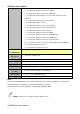
SEAX-H81 User’s Manual 3.3 Using Setup In general, you use the arrow keys to highlight items, press to select, use the PageUp and PageDown keys to change entries, press for help and press to quit. The following table provides more detail about how to navigate in the Setup program using the keyboard.
SEAX-H81 User’s Manual 3.4 Getting Help Press F1 to pop up a small help window that describes the appropriate keys to use and the possible selections for the highlighted item. To exit the Help Window press or the F1 key again. 3.5 In Case of Problems If, after making and saving system changes with Setup, you discover that your computer no longer is able to boot, the BIOS supports an override to the NVRAM settings which resets your system to its defaults.
SEAX-H81 User’s Manual 3.6 BIOS setup Once you enter the BIOS Setup Utility, the Main Menu will appear on the screen. The Main Menu allows you to select from several setup functions and exit choices. Use the arrow keys to select among the items and press to accept and enter the sub-menu. 3.6.1 Main Menu This section allows you to record some basic hardware configurations in your computer and set the system clock. 3.6.1.1 System Language Use this option to select system language 3.6.1.
SEAX-H81 User’s Manual 3.6.2 Advanced BIOS settings This section allows you to configure your CPU and other system devices for basic operation through the following sub-menus. 3.6.2.1 ACPI Settings Item Options Enable ACPI Auto Configuration Disabled[Default] Enabled Enable Hibernation Disabled Description Enable or Disable BIOS ACPI Auto Configuration.
SEAX-H81 User’s Manual Enabled[Default] S3 Video Repost ACPI Sleep State Hibernate (OS/S4 Sleep State). This option may be not effective with some OS. Disabled[Default] Enabled Suspend Disabled S1 only(CPU Stop Clock) S3 only(Suspend to RAM) [Default] Enable or Disable S3 Video Repost. Select ACPI sleep state the system will enter when the SUSPEND button is pressed. 3.6.2.
SEAX-H81 User’s Manual 3.6.2.2.1 USB Configuration Item Options Legacy USB Support Enabled[Default] Disabled Auto XHCI Hand-off Disabled Enabled[Default] EHCI Hand-off Disabled[Default] Enabled USB Mass Storage Driver Support USB transfer time-out Device reset time-out Device power-up delay Disabled Enabled[Default] 1 sec 5 sec 10 sec 20 sec[Default] 10 sec 20 sec[Default] 30 sec 40 sec Auto[Default] Manual Description Enables Legacy USB support.
SEAX-H81 User’s Manual 3.6.2.3 CPU Configuration Use the CPU configuration menu to view detailed CPU specification and configure the CPU. Item Options Hyper-threading Disabled Enabled[Default] Active Processor Cores Limit CPUID Maximum All[Default] 1 2 3 Disabled[Default] Enabled 34 SEAX-H81 User’s Manual Description Enabled for Windows XP and Linux. When Disabled only one thread per enabled core is enabled. Number of cores to enable in each processor package. Disabled for Windows XP.
SEAX-H81 User’s Manual Execute Disable Bit Intel Virtualization Technology Enhanced C1 state CPU C3/6 Report CPU C7 Report Disabled Enabled[Default] Disabled Enabled[Default] Disabled Enabled[Default] Disabled Enabled[Default] Disabled CPU C7 CPU C7s[Default] XD can prevent certain classes of malicious buffer overflow attacks when combined with a supporting OS (Windows Server 2003 SP1, Windows XP SP2, SuSE Linux 9.2, RedHat Enterprise 3 Update 3.
SEAX-H81 User’s Manual 3.6.2.5 PCH-FW Configuration Item MEBx Type MDES BIOS Status Code Firmware Update Configuration Options None[Default] MiniMEBx Disabled[Default] Enabled MEBx Type. Enable/Disable MDES BIOS Status Code. Configure Management Engine Technology Parameters. 3.6.2.5.
SEAX-H81 User’s Manual Item Options Me FW Image Re-Flash Disabled[Default] Enabled Description Enable/Disable Me FW Image Re-Flash function. 3.6.2.
SEAX-H81 User’s Manual 3.6.2.7 NCT6779D Super IO Configuration 3.6.2.7.1 Serial Port 0 Configuration Item Serial Port Change Settings Options Enabled[Default], Disabled Auto[Default] IO=3F8h; IRQ=4; IO=3F8h; IRQ=3,4,5,6,7,10,11,12; IO=2F8h; IRQ=3,4,5,6,7,10,11,12; IO=3E8h; IRQ=3,4,5,6,7,10,11,12; IO=2E8h; IRQ=3,4,5,6,7,10,11,12; 38 SEAX-H81 User’s Manual Description Enable or Disable Serial Port (COM). Select an optimal setting for Super IO device.
SEAX-H81 User’s Manual 3.6.2.7.2 Serial Port 1 Configuration Item Serial Port Change Settings Device Mode Options Enabled[Default], Disabled Auto[Default] IO=2F8h; IRQ=3; IO=3F8h; IRQ=3,4,5,6,7,10,11,12; IO=2F8h; IRQ=3,4,5,6,7,10,11,12; IO=3E8h; IRQ=3,4,5,6,7,10,11,12; IO=2E8h; IRQ=3,4,5,6,7,10,11,12; Standard Serial Port Mode[Default] Full Duplex, ASKIR Mode Half Duplex, ASKIR Mode Description Enable or Disable Serial Port (COM). Select an optimal setting for Super IO device.
SEAX-H81 User’s Manual 3.6.2.7.3 Parallel Port Configuration Item Parallel Port Change Settings Device Mode Options Enabled[Default], Disabled Auto[Default] IO=378h; IRQ=5; IO=378h; IRQ=5,6,7,10,11,12; IO=278h; IRQ=5,6,7,10,11,12; IO=3BCh; IRQ=5,6,7,10,11,12; STD Printer Mode[Default] SPP Mode EPP-1.9 and SPP Mode 40 SEAX-H81 User’s Manual Description Enable or Disable Parallel Port (LPT/LPTE). Select an optimal setting for Super IO device. Change the Printer Port mode.
SEAX-H81 User’s Manual EPP-1.7 and SPP Mode ECP Mode ECP and EPP 1.9 Mode ECP and EPP 1.7 Mode 3.6.2.8 HW Monitor The H/W Monitor shows the operating temperature, fan speeds and system voltages. Item CPU Smart Fan Option Description Enable or Disable CPU Smart Fan. T1:30°C Duty:55T2:40°C Duty:70T3:50°C Duty:80T4:60°C Duty:90risis:70°C Duty:100 PWM Output 0-100 Set CPU Fan Speed. 3.6.2.
SEAX-H81 User’s Manual Item Watchdog Count Mode Watchdog Timeout Value Option Second[Default] Minute 0 Description Watchdog Count Mode Selection. Fill Watchdog Timeout Value, 0 means disabled. 3.6.2.10 AMI Graphic Output Protocol Policy Item Option Output Select Unknown Device Output Interface. BIST Enable Disabled[Default] Enabled Starts or stops the BIST on the integrated display panel.
SEAX-H81 User’s Manual 3.6.3 Chipset Item Description South Bridge Configuration PCH Parameters. North Bridge Configuration System Agent (SA) Parameters. 3.6.3.
SEAX-H81 User’s Manual Item Options SATA Controller(s) Disabled Enabled[Default] SATA Mode Selection IDE[Default] AHCI RAID LPC Bus[Default] Port 80h Redirection PCIE Bus Description Enable or disable SATA Device. Determines how SATA controller(s) operate. Control where the Port 80h cycles are sent. 3.6.3.
SEAX-H81 User’s Manual [448M] [480M] [512M] [1024M] [128M] DVMT Total Gfx Mem [256M][Default] [MAX] 3.6.4 Select DVMT 5.0 Total Graphics Memory size used by the Internal Graphics Device. Boot settings Item Option Setup Prompt Timeout 1~65535 Bootup NumLock State Full Screen Logo On[Default] Off Disabled Enabled[Default] Description Number of seconds to wait for setup activation key. 65535(0xFFFF) means indefinite waiting. Select the keyboard NumLock state. Enables or disables Quiet Boot option.
SEAX-H81 User’s Manual 3.6.4.
SEAX-H81 User’s Manual 3.6.5 Security Use the Security menu to set system and user password. 3.6.5.1 Administrator Password This setting specifies a password that must be entered to access the BIOS Setup Utility. If only the Administrator's password is set, then this only limits access to the BIOS setup program and is only asked for when entering the BIOS setup program. By default, no password is specified.
SEAX-H81 User’s Manual 3.6.6 Performance 3.6.6.1 CPU Configuration Item Options Non Turbo Ratio Override 0-21[Default] IA Core Current Max (1/8 Amp) 0 48 SEAX-H81 User’s Manual Description Non Turbo Ratio Override. IA Core Current Max (1/8 Amp).
SEAX-H81 User’s Manual Enhanced Intel SpeedStep Technology Disabled Enabled[Default] Graphics Core Ratio Limit 0-10[Default] Enhanced Intel SpeedStep Technology. Graphics Core Ratio Limit. 3.6.6.2 North Bridge Configuration Item Options Performance Memory Profiles Automatic[Default] Manual XMP Profile 1 XMP Profile 2 Description The selection of Performance Memory Profiles which impacts memory sizing behavior.
SEAX-H81 User’s Manual 3.6.6.3 OverVoltage Configuration Item Options Memory Voltage (I/O) 1.50V[Default] 1.55V 1.60V 1.65V SVID Override Voltage Target(mV) 0 SVID Override Voltage Target, up to 2500mV. CPU Voltage Offset(mV) 0 CPU Voltage Offset, 0mV-998mV. GT Voltage Offset (mV) 0 GT Voltage Offset, 0mV-998mV. 50 SEAX-H81 User’s Manual Description Set memory voltage.
SEAX-H81 User’s Manual 4. Drivers Installation Note: Installation procedures and screen shots in this section are for your reference and may not be exactly the same as shown on your screen.
SEAX-H81 User’s Manual 4.1 Install Chipset Driver Insert the Supporting DVD-ROM to DVD-ROM drive, and it should show the index page of Avalue’s products automatically. If not, locate Index.htm and choose the product from the menu left, or link to \Driver_Chipset\Intel\SEAX-H81. Note: The installation procedures and screen shots in this section are based on Windows 7 operating system. Step 3. Select Install. Step 1. Select Next to continue installation. Step 2. Select Accept to the next step.
SEAX-H81 User’s Manual 4.2 Install VGA Driver Insert the Supporting DVD-ROM to DVD-ROM drive, and it should show the index page of Avalue’s products automatically. If not, locate Index.htm and choose the product from the menu left, or link to \VGA\SEAX-H81_VGA. Note: The installation procedures and screen shots in this section are based on Windows 7 operating system. Step 3. Select Next to continue installation. Step 4. Select Next. Step 1. Select Next to start setup. Step 2.
SEAX-H81 User’s Manual 4.3 Install LAN Driver (For Realtek 8111E Gigabit Ethernet) Insert the Supporting DVD-ROM to DVD-ROM drive, and it should show the index page of Avalue’s products automatically. If not, locate Index.htm and choose the product from the menu left, or link to \Driver_Gigabit\Realtek\RTL8111E\SEAXH81_LAN. Note: The installation procedures and screen shots in this section are based on Windows 7 operation system. Step 1. Click Next to Install. Step 2.
SEAX-H81 User’s Manual 4.4 Install Audio Driver (For Realtek ALC662 HD Audio) Insert the Supporting DVD-ROM to DVD-ROM drive, and it should show the index page of Avalue’s products automatically. If not, locate Index.htm and choose the product from the menu left, or link to \Driver_Audio\Realtek\ALC662\SEAX-H81_Audio. Note: The installation procedures and screen shots in this section are based on Windows 7 operation system.
SEAX-H81 User’s Manual 4.5 Install USB3.0 Driver Insert the Supporting DVD-ROM to DVD-ROM drive, and it should show the index page of Avalue’s products automatically. If not, locate Index.htm and choose the product from the menu left, or link to \Utility\SEAX-H81_USB3.0. Note: The installation procedures and screen shots in this section are based on Windows 7 operating system. Step 3. Select Next to continue installation. Step 1. Select Next to start setup. Step 2. Select Yes to the next step.
SEAX-H81 User’s Manual 4.6 Install ME Driver Insert the Supporting DVD-ROM to DVD-ROM drive, and it should show the index page of Avalue’s products automatically. If not, locate Index.htm and choose the product from the menu left, or link to \Utility\SEAX-H81_ME. Note: The installation procedures and screen shots in this section are based on Windows 7 operating system. Step 3. Select Next to continue installation. Step 1. Select Next to start setup. Step 4. Select Finish to complete Installation.
SEAX-H81 User’s Manual 5.
SEAX-H81 User’s Manual Unit: mm SEAX-H81 User’s Manual 59
SEAX-H81 User’s Manual Unit: mm 60 SEAX-H81 User’s Manual