SMA-IMX6 Freescale i.MX 6 ARM Cortex-A9 RISC Module User’s Manual 1st Ed – 17 October 2014 Part No.
SMA-IMX6 User’s Manual FCC Statement THIS DEVICE COMPLIES WITH PART 15 FCC RULES. OPERATION IS SUBJECT TO THE FOLLOWING TWO CONDITIONS: (1) THIS DEVICE MAY NOT CAUSE HARMFUL INTERFERENCE. (2) THIS DEVICE MUST ACCEPT ANY INTERFERENCE RECEIVED INCLUDING INTERFERENCE THAT MAY CAUSE UNDESIRED OPERATION. THIS EQUIPMENT HAS BEEN TESTED AND FOUND TO COMPLY WITH THE LIMITS FOR A CLASS "A" DIGITAL DEVICE, PURSUANT TO PART 15 OF THE FCC RULES.
User’s Manual Content 1. Getting Started ............................................................................................................ 4 1.1 Safety Precautions .................................................................................................... 4 1.2 Packing List ............................................................................................................... 4 1.3 Document Amendment History .......................................................................
SMA-IMX6 User’s Manual 1. Getting Started 1.1 Safety Precautions Warning! Always completely disconnect the power cord from your chassis whenever you work with the hardware. Do not make connections while the power is on. Sensitive electronic components can be damaged by sudden power surges. Only experienced electronics personnel should open the PC chassis. Caution! Always ground yourself to remove any static charge before touching the CPU card.
User’s Manual 1.
SMA-IMX6 User’s Manual 1.4 Manual Objectives This manual describes in details Avalue Technology SMA-IMX6 Single Board. We have tried to include as much information as possible but we have not duplicated information that is provided in the standard IBM Technical References, unless it proved to be necessary to aid in the understanding of this board. We strongly recommend that you study this manual carefully before attempting to set up SMA-IMX6 series or change the standard configurations.
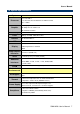
User’s Manual 1.5 System Specifications System Freescale i.MX 6 Processor Solo, Dual Lite, Dual and Quad Core ARM Cortex-A9 Up to 1.2GHz Dual Display Graphics HD 1080p Encode and Decode 2D and 3D Acceleration Memory Flash Ethernet USB DDR3L 512MB ~ 2GB 4GB (Up to 64GB) eMMC On-module 10/100/1000 Mbit/sec 2 x USB 2.
SMA-IMX6 User’s Manual 1.6 Architecture Overview—Block Diagram The following block diagram shows the architecture and main components of SMA-IMX6.
User’s Manual 2.
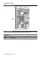
SMA-IMX6 User’s Manual 2.1 Product Overview 2.2 Connector List The following tables list the function of each of the board’s connectors.
User’s Manual 2.3 Setting Connectors 2.3.
SMA-IMX6 User’s Manual Signal PIN PIN Signal Signal PIN PIN Signal SATA_RX- P52 S53 I2S2_CK PCIE_A_REFCK+ P83 S84 PCIE_B_REFCK+ GND P53 S54 SATA_ACT# PCIE_A_REFCK- P84 S85 PCIE_B_REFCK- SPI1_CS0# P54 S55 AFB8_PTIO GND P85 S86 GND SPI1_CS1# P55 S56 AFB9_PTIO PCIE_A_RX+ P86 S87 PCIE_B_RX+ SPI1_CK P56 S57 PCAM_ON_CSI0# PCIE_A_RX- P87 S88 PCIE_B_RX- SPI1_DIN P57 S58 PCAM_ON_CSI1# GND P88 S89 GND SPI1_DO P58 S59 SPDIF_OUT PCIE_A_TX+ P89 S90 PCIE_B_TX+ GND P
User’s Manual Signal PIN PIN Signal Signal PIN PIN Signal GPIO6 / TACHIN P114 S115 LCD_D20 CAN0_TX P143 S144 RSVD / EDP_HPD GPIO7 / PCAM_FLD P115 S116 LCD_D21 CAN0_RX P144 S145 WDT_TIME_OUT# GPIO8 / CAN0_ERR# P116 S117 LCD_D22 CAN1_TX P145 S146 PCIE_WAKE# GPIO9 / CAN1_ERR# P117 S118 LCD_D23 CAN1_RX P146 S147 VDD_RTC GPIO10 P118 S119 GND VDD_IN P147 S148 LID# GPIO11 P119 S120 LCD_DE VDD_IN P148 S149 SLEEP# GND P120 S121 LCD_VS VDD_IN P149 S150 VIN_PWR_BAD# I2C_P
SMA-IMX6 User’s Manual 3.
User’s Manual 3.1 Download Source code for building Ubuntu image file Please make a folder for storing the source code first then typing the command below to get started for the source code download. $ Sudo apt-get install git $ git clone guest@202.55.227.57:freescale/core.git -b SMARC About password, please check with Avalue Sales or PM to get it. 3.2 Set up a Linux host for building U-boot & Kernel Image We support to compile u-boot & Kernel on Ubuntu 12.
SMA-IMX6 User’s Manual 3. You can find the u-boot(u-boot.bin) & Kernel(uImage) under folder ”core” as below after the compiling is finish. PS: If you would like to use Mfgtool for flashing image file, you must put the file u-boot.bin and uImage under “~\Image\smarc” for right detected path.
User’s Manual 3.4 Use MfgTool to flash Ubuntu into onboard eMMC Manufacturing tool, a successor of ATK, provides a series of new features to power your mass production work. The features like windows style GUI, multiple devices support, explicit status monitoring, versatile functionalities and highly flexible architecture make it a best choice to meet your critical timing, cost and customization requirements. For using Mfgtool to flash image file into onboard eMMC, please follow up the steps below 1.
SMA-IMX6 User’s Manual 5. Select the MCU option by name, if the MCU of module board is “i.MX6 Solo”, please click “MX6DL Linux Update”, and click “Linux-ubuntu” (Ubuntu GUI version) for the OS of flashing, then click “Run MFG Tool”. Or the if the MCU of module board is “i.MX6 Quad core”, please click “MX6Q Linux Update”, and click “Linux-ubuntu” (Ubuntu GUI version) for the OS of flashing, then click “Run MFG Tool”. 6.
User’s Manual 7. Click “Start” to flash image file. 8. It will show “Done” after flashing is finish, then click “Stop” and “Exit” to close the screen. 9. You can also get the information from Terminal (debug portCOM1) after flashing is finish.
SMA-IMX6 User’s Manual 3.5 Create a bootable SD card with Ubuntu 12.04 file system Please insert a SD card in the card reader on your Linux host PC 1) Check device node of your SD card by command below.
User’s Manual $ sudo umount /dev/sdd1 $ sudo mount /dev/sdd1 /mnt $ cd /mnt $ sudo tar jxvpf ~/ubuntu.tar.bz2 $ cd $ sudo umount /dev/sdd1 The Ubuntu file system content is now on the SD card. You can insert it to mainboard then turn on the DIP switch pin2&3 as below for booting.
SMA-IMX6 User’s Manual 3.6 Bootloader settings for booting from SD card 1) Please turn on the Pin 2&3 of the DIP switch as below for booting from SD card . 2) 3) 4) Insert SD card on SD socket. Connect RS232 cross over cable from COM1 of mianboard to COM port of Host PC. Run hyper terminal program on Host PC (teraterm on Windows or minicom on Linux) Power on mainboard and press ”space” key to get into bootloader menu.
User’s Manual SMARC U-Boot >setenv linux_cmd ‘setenv bootargs ${linux_bootargs};mmc dev 1;mmc read ${loadaddr} 0x800 0x3000;bootm’ SMARC U-Boot > setenv linux_bootargs 'console=tty0 console=ttymxc0,115200 root=/dev/mmcblk1p1 rootwait rw' SMARC U-Boot> saveenv SMARC U-Boot> boot SMA-IMX6 User’s Manual 23
SMA-IMX6 User’s Manual 3.7 Bootloader settings for booting from onboard eMMC 1) Please turn on the Pin 1 of the DIP switch as below for booting from onboard eMMC. 2) Insert SD card on SD socket. Connect RS232 cross over cable from COM1 of mianboard to COM port of Host PC. Run hyper terminal program on Host PC (teraterm on Windows or minicom on Linux) Power on mainboard and press ”space” key to get into bootloader menu.
User’s Manual SMARC U-Boot > setenv linux_bootargs 'console=tty0 console=ttymxc0,115200 root=/dev/mmcblk0p1 rootwait rw' SMARC U-Boot> saveenv SMARC U-Boot> boot SMA-IMX6 User’s Manual 25
SMA-IMX6 User’s Manual 3.8 Display output application of IMX6 This section describes how to setup the display output for LVDS, HDMI, VGA of IMX6 module. 1. You can find the file of resolution setup of LVDS&VGA under the directory ”..~/core/kernel/drivers/video/mxc”, for LVDS is ”ldb.c”, and for VGA is ” mxc_lcdif.c”. ”ldb.c” ”mxc_lcdif.c” 2. You need to fill the resolution parameter(.mode_str) on the file ”rev_sa01.
User’s Manual 3. Finally, you should fill the parameter for booting on the file ”mx6_smarc.h” under the directory ”~/core/u-boot/include/configs/”. Please add ”video=mxcfb0:dev=display name” on the column 132 "rootwait rw \0" to enable display output function when booting. 4. Please refer ch1.3 to re-build the u-boot &Kernel binary file for booting. Note: If you need to use double display output in Ubuntu, you should setup the ” rev_sa01.
SMA-IMX6 User’s Manual video=mxcfb1:dev=second display neme” to mx6_smarc.h, but for this application, you also need to write a program for controling the second diplay first or the second display will not enable after you follow up all the setting above.
User’s Manual 3.9 Download Android Source Code for building image file Please make a folder for storing the source code first then typing the command below to get started for the source code download. $ sudo apt-get install git $ git clone guest@202.55.227.57:freescale/imx6/Android.git -b 4.4.2-SMARC About password, please check with Avalue Sales or PM to get it. 3.10 Set up for building Android image file We support to compile u-boot & Kernel on Ubuntu 12.
SMA-IMX6 User’s Manual 3.11 Building up Android image file You can follow up the steps below to compile Android image file after download the source code. 1. Please move to the folder ”Android” then start to compile image file. 2. Type the command to compile image file. $ ./run.sh –j16 (-j number means multi jobs for more efficiant building, you can add it according to your CPU performance of PC, e.g. mine is ”–j16” as below ). 3. You can find the finished image file(u-boot-6q.bin, u-boot-6solo.
User’s Manual 3.12 Use MfgTool to flash Android into onboard eMMC Manufacturing tool, a successor of ATK, provides a series of new features to power your mass production work. The features like windows style GUI, multiple devices support, explicit status monitoring, versatile functionalities and highly flexible architecture make it a best choice to meet your critical timing, cost and customization requirements.
SMA-IMX6 User’s Manual On the other hand, if the MCU of module board is “i.MX6 Quad core”, please click the folder “~\ MX6Q-IMX6” to flash image file, e.g. mine is D:\ MFG-REV-SA01_Image\ MX6Q-IMX6” 4) Click “MfgTool2.exe” to flash image file into smarc module. 5) Click “Start” to flash image file. 6) It will show “Done” after flashing is finish, then click “Stop” and “Exit” to close the screen.
User’s Manual 7) You can also get the information from Terminal (debug portCOM1) after flashing is finish.