
User Guide


1.8 Test & Commission.
After the wiring has been completed re-connect the
battery to the terminals marked Batt + -
The panel will now go into alarm condition, enter user
code (0123) to silence, the Tamper and Power will be lit
and Day & Zone LED’s flashing.
To reset the panel re-enter the user code and the Day &
Power LED’s will be steady (DAY mode).
Re-fit the lower cover and the system should now be
tested to ensure correct operation.
2 Descriptions
2.1 Zones
Avanti panels come supplied with service links fitted to
the zone terminals to simulate a closed circuit. As each
zone is connected these links should be removed. All
zones are fully programmable.
Zone Functions per Program:
Immediate – This function would be used when the
zone is not part of an entry/exit route. When the system
is SET activation of an immediate zone will cause a full
alarm condition.
Timed – A timed zone would be used to protect an
entry/exit route. Opening the door or triggering the
sensor in this type of zone when the system is SET will
start the entry timer.
Time Inhibited – A time inhibited zone operates as an
immediate zone unless a timed zone has been operated
and a timer started. Such a zone would be utilised to
allow passage between the entry/exit door and the control
panel when there are detectors present.
Fire – If you choose to utilise a zone as a fire zone then
no other devices may be wired into this zone. Therefore a
zone cannot be both fire and intruder.
Doorbell –this feature can be programmed into any
zone. A doorbell will not operate whilst the entry/exit
timers have started, when the system is in full alarm
condition or whilst in programming mode.
Exit Modes per Program:
Timed Exit – a timed program will SET once the exit
timer has expired.
Final Door Set – a final door program will SET 5
seconds after the final door has been opened and closed.
Immediate/Silent Set – an immediate program will
SET the system immediately and silently.
2.2 Tamper
Avanti panels come supplied with a service link fitted to
the Tamper terminals; this should be removed as the
tamper circuit is wired.
Tamper circuits must be wired in series.
If a Tamper occurs whilst the system is in DAY mode
then only the internal sounders will be activated.
If a Tamper occurs whilst the system is SET then both the
internal and external sounders will be activated. (If you
are using an RS Panel fitted with a communicator then a
signal will also be sent to an Alarm Receiving Centre
(ARC).
2.3 PA
Remove the service link and wire in series any number of
PA buttons to the PA terminals. Activation of the PA will
cause the system to go into a full alarm condition whether
in DAY mode or SET. (If you are using an RS Panel
fitted with a communicator then a signal will also be sent)
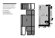
2.4 Bell output & Strobe
Connect the wires from the bell to the terminals D (bell
positive) and B (bell negative).
The bell tamper should be wired to the T A terminals and
the service link removed.
Wire the strobe to the terminals marked strobe observing
the correct polarity.
When fitting a combined sounder/strobe unit follow
manufactures instructions.
• T -Ve tamper return
• A -Ve supply (0V)
• B -Ve sounder trigger
• D +Ve supply (12V)
2.5 Internal sounder
A maximum of two 16 ohm extension speakers may be
wired in parallel to the terminals marked The
volume of both the internal sounder and entry/exit timers
can be adjusted by a pre-set located on the PCB.
2.6 Set +
This output becomes 12V positive on SET and is removed
on commencement of the entry timer.
2.7 13V Supply
This terminal provides a 13.8V output to power detectors
and shock sensors etc. Total current available is 350 mA.
2.8 PTS
The PTS terminals can be programmed to be either
PUSH TO SET (PTS) or KEYSWITCH operation.
PTS – operation of an exit terminate button when exiting
the property will cause the timer to expire immediately
and the system will become SET.
Keyswitch – this enables the system to be SET and
UNSET with the use of a keyswitch. If the panel needs to
be reset then a user code must be entered.
2.9 Battery
To ensure continuing protection in the event of mains
power failure a suitable rechargeable battery with a
capacity to support the system for a period of 12 hours
must be fitted.
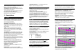
NOTE: Calculations made for Avanti Compact with
onboard keypad using a neon sounder, assuming 1
complete alarm cycle of 20 minutes.
Battery Backup Time Vs. Number of Passives (Passive
Current=15ma)
4
9
14
19
12345678
Nu m b e r o f P a ssi ve s
Backup Time in Hours
1.2Ah Battery
2.1Ah Battery
Battery Backup Time Vs. Number of Passives (Passive
Current=10ma)
4
9
14
19
12345678
Number of Passives
Backup Time in Hours
1.2Ah Battery
2.1Ah Battery