
User`s manual

17
User’s Manual
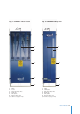
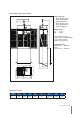
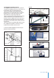
Fig. 8
Safety brake
BSO OSL500
4.7 Cabin safety devices
4.7.1 Safety brake
Electromagnetic spring-loaded brake which
engages automatically
– on releasing the up/down push button and
– following a power failure.
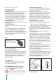
4.7.2 EMERGENCY STOP
When the red EMERGENCY STOP (pendant
control) switch is pushed in an emergency, all
control is interrupted. After remedying the fault,
control is reactivated by turning the switch clock-
wise, until it pops out again.
4.7.3 EMERGENCY STOP fixed (optional)
Only in service lifts with AUTOMATIC function
installed. A backup switch to the pendant control
EMERGENCY STOP switch is situated on one of
the side panels inside the lift. For function, see
above (Fig. 9).
4.7.4 Automatic operation switch
A switch situated inside the pendant control
holder. It prevents the lift from being controlled
from the inside when the control is in automatic
mode.
4.7.5 Mechanical lifting force limiter
The lifting force limiter is built into the wire traction
system and will prevent upward travel in the event
of an overload. A warning signal (buzzer) is
triggered which will stop only when the cause of
the overload has been removed.
Possible reasons for activation of the limiter:
- The service lift is overloaded or
- The service lift encounters an obstacle during
upward travel.
Operator intervention:
- Reduce the load to below the overload limit, or
- lower the lift until it is free of the obstacle and
remove the obstacle before using the lift again.
4.7.6 Safety gripping device
Hoistable personal transportation means must be
equipped with 2 safety gripping devices which will
prevent the load from falling.
Safety brake Type BSO + OSL
The safety brake BSO + OSL safety gripping
devices are opened manually (Fig. 8).
The speed of the safety wire
passing through the device is continuously
monitored, and the jaws automatically close in the
event of sudden excessive speed.
This protects the lift from
a) Lifting wire breaks and
b) Hoist failures.
The safety gripping device can also be engaged
manually in an emergency by pressing the Emer-
gency stop button. The window is used to monitor
the centrifugal force mechanism’s function during
operation. For information on required
intervention when the safety gripping
device engages, see section 8 on page 24.
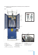
4.7.7 Drop down safety beam (Optional)
This device can be installed in sliding door lifts and
it protects against accidental fall when the door is
opened while working between platforms. The
beam remains in closed position by means of a
latch. The beam is opened by actuating on the
latch and lifting up slightly the beam. (Fig. 9c)
See in 4.6.10.1 Guard locking switch how to open
the sliding door between platforms.
4.7.8 Yellow flash (Optional)
An optional set of flashes can be mounted on the
top and at the base of the lift. The flashes indicate
when the lift is in movement (Fig 9a).
4.7.9 Emergency light (Optional)
An emergency light can be installed to illuminate
inside the lift with and without electric supply.
The operation modes can be selected
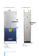
Stop
button
ON/Locked
OFF/Open
Window
Fig. 9
Emergency stop
and bottom stop
switch
Fig. 9a
Fixed
Emergency
stop button
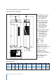
Stop
button
ON/Locked
OFF/Open
Window
Fig. 9b Fig. 9c
Automatic
operation
switch