
User`s manual

18
!
1
2
3
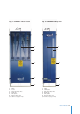
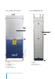
AVANTI Service Lift for Wind Turbines
by means of a switch. (Fig .9b)
4.7.10 Door stop switch
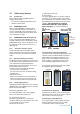
4.7.10.1 Sliding door:
Sliding door is closed by pushing the actuator into the
door guard locking switch. (Fig .15) The switch is
unlocked by pushing the green button if the cabin is
located at a height corresponding to a platform. In
case of an emergency evacuation between platforms,
the interlock is unlocked by pushing its emergency
release red button from outside the cabin as well as
using a M5 triangular key from inside the cabin.
4.7.10.2 Double door:
A switch (Fig. 12) will interrupt control if the door is not
closed properly.
4.7.10.3 Half roller door:
A switch will interrupt control if the door is not closed
properly.
4.7.11 Trapped-Key interlock system (Optional):
Control is interrupted by turning the trapped-key
switch to OFF and then the key is able to be taken out.
The key allows the user to open the platform fence
doors. See the Trapped-Key Interlock System Manual
for further information.
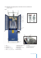
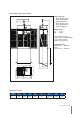
4.7.12 Limit stop switch
4.7.12.1 Top limit stop switch
At the top of the cabin frame a top limit stop switch will
stop upward travel when activated (Fig. 10). Down-
ward travel will still be possible. A top stop disc which
activates the top stop switch is installed below the
lifting wire attachment. (Fig. 5 section 2 of the
installation manual)
ATTENTION!
When the top limit stop switch is engaged,
activate the DOWN switch until the top limit
stop switch is released.
4.7.12.2 EMERGENCY top limit stop switch
Deactivates control if the top limit stop switch fails
(Fig. 10). Manual downward travel is possible.
CAUTION!
Do not use the service lift until the top
limit stop switch fault has been rectified.
4.7.12.3 Bottom safety stop
The bottom safety stop switch (Fig. 11a or Fig. 11b
which shows an optional configuration) stops down-
ward travel if the service lift
encounters an obstacle or touches the ground.
Upward travel will be possible, for instance to remove
the obstacle. In order to put the service lift on the
ground, the contact plate’s operation can be by-
passed with the key switch in the control box. If it is
possible to enter underneath the service lift a double
button safety stop must be installed.(See part 1 of the
installation manual).
4.7.12.4 Top safety stop (Optional)
The top safety stop switch stops upward travel if the
lift:
- Type 1: encounters an obstacle (fig. 13).
- Type 2: Besides, the switch works as top limit stop
switch. A top stop end bar is installed bellow the
guiding wire attachment and activates the top safety
stop. In this case the top stop end bar replaces the top
stop disc. (fig. 14)
Downward travel will be possible, for instance to
remove the obstacle.
4.8 Safety devices for fences with door
Safety devices for fences include devices to prevent
people to access to the service lift area unless the
service lift was in a safety condition of accessibility.
Besides, the device guarantees the service lift doesn’t
move any moment the protected fence doors were
open. There are two types of safety devices for fences:
4.8.1 Guard Locking System
The Guard Locking System uses a system of security
locking switches installed on the fences. Another
position switch detects the right position of the service
lift on the protected platform.
The service lift cannot operate until all the protected
fences are closed and locked.
The fences remain closed and locked until the service
lift is stopped and properly positioned on the platform,
actuating the position switch of the platform. In this
position, the guard locking can be unlocked while
pressing the green light button.
Consult the AVANTI Guard Locking System Manual
for further information.
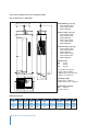
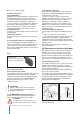
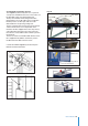
Fig. 15
1 Green push button
2 Emergency release red push button
3 Emergency release M5 triangular key
Position switch
Fence latch
with actuator
Green Light
access button
Locking
switch