
User`s manual

20
!
STOP
AVANTI Service Lift for Wind Turbines
If a safety device for fence doors is installed (see
chapter 4.7 of the User’s manual), every platform
fence door must be closed to be able to drive the
cabin.
5.1 Service lift
a) Before each operation, ensure that the traction
hoist, the safety brake and all auxiliary
components (stoppers, wire guide wheels, etc.)
are mounted in accordance with the specifications
and without any noticeable defects.
b) Check whether the drive, and safety wires are fed
correctly around the two wire guide wheels.
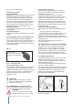
c) Wire ends (of 3 m or more in length) must be
coiled separately at the floor and tied with strips
in at least 3 places.
d) Check lifting capacity: (see the rating plate or
section 4.5.3) – the extra load (persons and
materials!) must not exceed the maximum rated
lifting capacity.
5.2 Operating area
a) Ensure that there are no obstacles within the
service lift’s operating area which may obstruct
the travel of the cabin or cause the cabin to hit the
ground.
b) Ensure that all relevant and required protection
measures below the cabin are in place. Such
measures could include pent roofs or barriers to
protect the staff from falling objects.
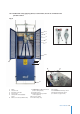
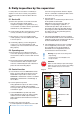
5.3 Control function
a) Close the doors. Press the EMERGENCY STOP
button. The lift should remain still when the UP/
DOWN button is pressed. To restart, turn the
EMERGENCY STOP button clockwise. If a FIXED
EMERGENCY STOP button is installed (Fig. 9)
test as above.
b) Test the top limit stop switch:
During upward travel, press the switch manually,
and the service lift should stop immediately.
Pressing the limit stop switch should enable the lift
to travel down again.
c) Test the EMERGENCY top limit stop switch:
During upward travel, press the switch manually,
and the service lift should stop immediately.
Neither upward nor downward travel should now
be possible.
d) Bottom safety stop. Lower the lift;
it should stop before the rubber feet of the cabin
reach the tower ground level. When the “bypass
switch” is activated, it should be possible to lower
the lift all the way to the ground.
e) Door stop switch:
Open the door - it should not be possible to move
the lift upwards or downwards.
Sliding door service lift: Move the cabin at a
height no corresponding to a platform - it
should not be possible to open the door. The
door will be only able to be opened by pushing
the emergency release red button from outside
the cabin as well as using a M5 triangular key
from inside the cabin.
f) If the optional AUTOMATIC function is installed.
Set the HAND/AUTOM. selector to AUTOM. When
holding the handle, the lift should remain still when
the UP or DOWN buttons are activated.
g) If the Trapped-Key interlock system is installed.
Turn the trapped-key switch to OFF - it should
be not possible to move the lift upwards or
downwards. See the Trapped-Key Interlock
System Manual for further information.
Warning! If any faults occur during work,
- stop working,
- if required secure the workplace and
- rectify the fault!
DANGER!
Make sure that nobody is exposed to danger
below the service lift, for instance from falling
parts. Suitable measures: Pent roof or
barriers.
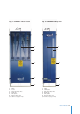
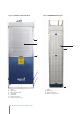
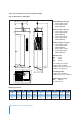
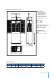
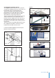
Fig. 13
Electrical control box
X402P/L502P M500
5. Daily inspection by the supervisor
HAND/
AUTOM.
(Optional)
Ready lamp
“ON”
Override
bottom
safety stop
EMERGENCY STOP
UP
DOWN
Pendant control