
Reference Guide


411-1333-922 Draft 01.03 November 2000
2
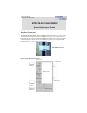
BTR 28-08 MMIC Specification
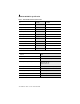
Table 1: BTR 28-08M Technical Specifications
TX IF Input RF Output
Frequency Range
2 8- 0 8M 500-650 MHz 27.50 - 27.65 GHz
Output Level (P1 dB)
26.25 dBm, -40° to +55° C
Output Level (IP3)
> +34.5 dBm
Input Impedance
50 Ohms
Input/Output Connector
N-Type Female WR-28 (non-standard hole pattern)
Input/Output VSWR 2.1:1, maximum 2.6:1, max (or 7 dB)
Gain (not including antenna) @ 25° C 30 ±1 dB, minimum
Gain vs. Temperature
±2.0 dB, (-40° to +55° C)
Gain Flatness
±2.0 dB over bandwidth
LO leakage
<-43 dBm (outband)
Frequency Stability
<±4 ppm, Over all Conditions
Antenna BTR
Frequency 27.5 - 31.3 GHz
Port-to-Port Isolation
55 dB (V/V); 55 dB (H/H)
Bore-sight Gain (Azimuth)
15.75±1.25 dBi, 90° Horn
18.9±1.25 dBi, 45°
23.8±1.3 dBi, 15°
Wave-guide Interface
WR-28 (non-standard hole pattern)
Mounted on transceiver housing
WR-28 flange
Size (Length x Height x Width)
10" x 9" x 2" (90°)
Polarity
single polarity H/H and V/V
Sectorized Angle Available
15°, 45°, and 90°