
Product Info


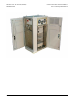
Table Of Contents
- FCC ID AB6NT1900FRM
- NORTEL CDMA METRO CELL
- (MetroDE -- MetroRE)
- 800/1900 MHz
- Outdoor Cell Site Requirements
- Issue 0.02
- Document: NORTEL CDMA Metro Cell (MetroDE -- MetroRE)
- Cell Site Requirements
- February, 2001
- NORTEL Wireless Networks
- CDMA BTS Radio Development
- BTS Radio Systems 2M41
- Security Warning:
- The information contained in this document is the property of Northern Telecom
- Ltd. The holder of this document shall keep all information contained herein
- confidential and shall protect the same in whole or in part from disclosure and
- dissemination to all third parties.
- Table of Contents
- 1.0 Executive Summary
- 2.0 Introduction
- This document outlines the cell site engineering requirements for the CDMA MCBTS 1900 System. Its...
- Specifications in the Product Specification |agreement (PSA) shall take precedence over informati...
- The MCBTS cell site requirements fall into six main categories:
- The mechanical requirements cover the physical characteristics (weight, size), the mounting requi...
- The MCBTS (Metrocell) will be deployed in a number of environments potentially both indoors and o...
- 3.0 Environmental Requirements
- 4.0 Mechanical Requirements
- 4.1 Physical Specifications
- 4.2 Digital Enclosure
- 4.3 Digital Enclosure Interface
- 4.4 External Battery Cabinet
- 4.5 General Cabinet Anchoring
- 4.6 Pad mounting
- 4.7 Rubber Isolation Pad
- 5.0 AC Power Requirements
- 5.1 Power Specifications
- Commercial AC power will be supplied to the DE as a single/split-phase, 120/240 Vac nominal, or 1...
- The DE ac power input requirements are as follows:
- • Nominal Input Voltage: 240/120 Vac, single, split phase, 50/60 Hz
- • Input Voltage Range: 178 to 264 Vac
- • Input Frequency: 47 - 63 Hz
- • Power factor: greater than 90% at nominal line voltage and frequency
- • Input current rating 70A, 2-pole circuit breaker
- 5.2 AC Power Connection
- 5.1 Power Specifications
- 6.0 RF Overlay Requirements
- The Metro Cell has several overlay options
- Basic installation configuration (single channel)
- Simple overlay or mini configuration
- The Metro Cell can accommodate 1900 MHz FRM’s, 800 MHz FRM’s, or combinations of both.
- The FRM is illustrated in Figure 16. Each FRM consists of the following main
- components: duplexer pre-selector module (DPM) or triplexer module, transmit receive
- module (TRM), power amplifier module (PAM) and fan/plenum assembly. The alarm
- indicator module (AIM) is located within the fan unit housing. The PAM, TRM, and fan
- unit have the same mechanical dimensions for both 800 MHz and 1900 MHz
- configurations. The 800 MHz DPM is taller than the 1900 MHz DPM.
- The minimum requirement (1 carrier) is 2 antennas per sector, one for the main path (Tx and one d...
- Table 6.1:
- 6.1 Cable Connections
- The optical link cable, SFRM DC power cable and the GPS antenna cable have a provisionable length...
- The quantity of inter-DFRM cables required depends upon the application. In a single carrier syst...
- Two sample configurations will be considered for illustrative purposes. These are:
- i) a basic system with no redundancy;
- ii) a premium system with all redundancy
- 7.0 GPS Receiver
- Timing and frequency reference information provided by the GPS receiver is critical to the proper...
- The antenna should be installed to provide the best view of the entire sky. A complete view of th...
- The maximum distance between Metrocell and GPS antenna is set by the maximum allowable cable loss...
- Connections and Cabling
- 8.0 Connections and Cabling
- 8.1 FRM Power Connections and Cables
- DC power is conducted to individual FRMs via two conductor (-48V, BR) shielded (ground) cables, o...
- The specifications for these external FRM dc cables are as follows:
- • less than 3000 feet, use 2 conductor #8 AWG shielded cable
- • Between 300 and 600 feet, use 2 conductor #6
- • Allowed cable voltage drop: 6 Vdc maximum (-48V and Rtn combined)
- • Cable terminations: two-hole lugs at the DEI BRR plate, twist-lock type
- connector at FRM (to mate with the PEM)
- • Shield termination: grounded at both the FRM and DEI ends, and at the base of
- the tower
- The FRM DC cable is sized for voltage drop, not ampacity
- The optical link enters the FRM via the electro-optic module (EOM)
- 8.2 FRM Interconnect
- 8.3 Fiber
- 8.1 FRM Power Connections and Cables
- 9.0 T1/E1 Connections
- The CM module has up to 6T1 interfaces connected through the backplane. The cable will probably b...
- The Metro Cell can be connected to the BSC using 1 to 6 T1/E1 links. These T1/E1 links are distri...
- There are two ways of connecting T1/E1 to the Metro Cell. The T1/E1 cables can be
- directly brought into the DEI or they can be connected to a RJ48H connector which
- interfaces with the DEI. The RJ48H connector cable NTGS0106 is provisionable. In the
- DEI T1/E1 connections are done on the middle and lower blocks among the three
- Telephone/Data Line Protection blocks as shown in Figure 87. The RJ48H connector is
- shown in Figure 88 and the pinout is shown in Table 30.
- The number of T1/E1s that need to be connected to the Metro Cell depends on the call
- carrying capacity of the T1/E1s and the number of calls that a Metro Cell has to make.
- The number of T1/E1 that need to be provisioned for a Metro Cell can be determined
- from Ref [10].
- The two modes of operation of Metro Cell are regular (or non-split) mode or split mode.
- In the regular mode only one DCG is active, the other DCG may not be provisioned or is
- a redundant DCG. In the split mode both DCGs are provisioned and are active. Each
- DCG in the split mode is a logical BTS. The T1/E1 connections of the Metro Cell in the
- regular and split mode are done as shown in Table 27.
- The T1/E1 lines are connected to one of the two BTSI cards in the control module (CM)
- Table 27: T1/E1 Connections of Metro Cell without Daisy Chaining
- The T1/E1 lines are connected to one of the two BTSI cards in the control module (CM)
- which forms part of the DCG. The connections are controlled by relays and are exclusive
- to one DCG. Therefore if T1/E1 #1 is connected to the first DCG then the same lines
- cannot be connected to the other DCG. This is true in regular as well as split mode. In
- regular mode since only one DCG is active, therefore, all the T1/E1s are connected to
- the active DCG. When the redundant DCG takes over then the connections are switched
- to it by closing the relays on this new active DCG and opening them on the previously
- active DCG. The middle column of Table 27 shows how the T1/E1 connections are done
- for the active DCG in regular mode. In the split mode each DCG is active and is part of
- the logical BTS. Therefore, each DCG has its own independent T1/E1 connections. The
- right column of Table 27 shows how the T1/E1 connections are done for the two logical
- BTSs in the split mode. It is clear from [1] that a single DCG, supporting a maximum of
- two carriers, does not need more than 3 T1/E1 connections. So, the connections shown
- in Table are reasonable and will provide for a redundant T1/E1 link per logical BTS in
- most cases (keeping in mind the number of T1/E1 links needed for 2 carriers as
- mentioned in [10]).
- The Metro Cell can be configured for a shorthaul link or a longhaul link. In case of a
- shorthaul configuration the Metro Cell should be within 655ft of the last repeater while for
- a longhaul link the Metro Cell should be within 6000ft of the last repeater using 22 gauge
- unshielded twisted pair cable i.e. 100 ohm 22 gauge cable. The shorthaul and longhaul
- link is configured using software. The distance of the Metro Cell from the last repeaterhas to ma...
- 10.0 Grounding
- 10.1 BTS grounding Architecture
- 10.2 Antenna Grounding
- 10.3 Radio rack Grounding
- The common ground point in the RE is the subframe. A #2 AWG cable will connect the
- subframe to the main ground point in the DEI in the side-by-side configuration. When the
- RE is installed remotely from the DEI/DE the ground cable will connect the subframe to
- the site ground in that area. Attachment shall be made with two hole compression lugs.
- The shield of the DC power cable connecting the main electronics cabinet to the FRM
- shall be grounded at both the FRM end and the main enclosure end (main ground plate)
- .
- Provision one NTGS0161 main site ground cable for the DEI/DE and one for every RE.
- 10.4 Site Ground Ring
- A peripheral grounding ring, usually buried around the site perimeter, or routed along the outer ...
- equipotential reference to minimize differential voltages during lightning surges. It
- consists of a #2 AWG (or larger) uninsulated, tinned copper conductor. Connections are
- made to it using C-tap clamps.
- The ground ring makes earth contact through ground electrodes, typically copper-clad
- stakes 3m (10 ft.) long, driven into the ground at 2.5 to 3m (8-10 ft.) intervals around the
- ground ring and tower, and welded to it. The resistance to earth of the ground ring shall
- be 25 ohms or less, with a preferred value of less than 5 ohms. See Nortel CS4122.00
- and DSAP65BA (Cell Site Power and Grounding) for further information.
- _____________________
- Fig. 10.1 Cell Site Grounding Connections
- 11.0 References
- [1] CMS-MTX/CDMA MCBTS 1900 Outdoor and MCBTS Base Platform. Product
- Specification Agreement. by Neil McGowan and Frank van Heeswyk.
- [2] CDMA MCBTS 1900 Outdoor. Power Protection and Grounding Design Specification.
- by Ed Norman
- .
- [3] CDMA MCBTS 1900 Outdoor. General Specification.
- [4] MCBTS 1900 MHz Radio Enclosure System Packaging Specification. by Fred Folk.
- [5] MCBTS Optical Link NTGS05AA, NTGS0117, NTGS0095 Functional Agreement.
- Packaging Concepts Methodology.
- [6] MCBTS Digital Enclosure Mechanical Assembly NTGS13AA Functional Agreement.
- Packaging Concepts Methodology.
- _____________________

METRO CELL OUTDOOR (DE/RE) CDMA BTS RADIO DEVELOPMENT
PROPRIETARY CELL SITE REQUIRE-
Feb. 2001 - 4 - Issue 01 Stream 00
1.0 Executive Summary
The CDMA Outdoor Metro Cell is a new product development for Nortel’s wireless mar-
kets in North America. Metrocell targets the high capacity market. This document details
cell site requirements for the Outdoor CDMA Metro Cell product. The Metro Cell can be
configured in a 800 MHz, 1900 MHz, or mixed frequency variants. The document
addresses initial deployment requirements and also covers future expansion require-
ments.