
Product Info

METRO CELL OUTDOOR (DE/RE) CDMA BTS RADIO DEVELOPMENT
PROPRIETARY CELL SITE REQUIREMENTS
Issue 01 Stream 00 - 7 - Feb. 2001
4.0 Mechanical Requirements
4.1 Physical Specifications
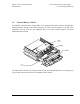
The MCBTS is comprised of a digital enclosure (DE) and radio frequency modules (FRM). The
digital enclosure is designed to be mounted on the ground while the FRMs are designed to be
installed in the radio enclosure (or radio rack).
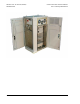
4.2 Digital Enclosure
The DE is the main structural component in the MCBTS. The digital enclosure will house the
rectifiers, equipment shelves, internal heating/cooling tray, heat exchanger internal loop fan
assembly and provide for all necessary internal cable routing management.
The preliminary outside dimensions for the DE are illustrated below. These dimensions refer to
the unpackaged height and are excluding the DEI which attaches to the left side and the heat
exchanger which mounts on the top.
The dimensions are:
• Depth: 30”
• Height: 57” Max (excluding 15” high heat exchanger)
• Width 30”
The DE with no shelves will weigh an estimated 190 lbs.
4.3 Digital Enclosure Interface
The Digital Enclosure Interface (DEI) for the MCBTS enclosure assembly provides entrance of
the AC power, network and alarm connections, and connection to the ground ring. The
dimensions of the DEI are shown below.
The dimensions are:
• Depth: 30” (same as overall depth of Digital Enclosure)
• Height: 72”
• Width 12”
The weight of the empty DEI is estimated to be 225 lbs. The loaded module weight after
integration of equipment is expected to be 700 lbs. Cable access to the DE is via DE interface
(DEI).