EXHIBIT 11 Reference Manual Applicant: Northern Telecom Ltd. For Certification on: AB6S8000 This document contains Proprietary Information of Northern Telecom Limited. This information is considered to be CONFIDENTIAL and should be treated appropriately.
Wireless Service Provider Solutions S8000 BTS Reference Manual PE/DCL/DD/0063 411–9001–063 12.
< 63 > : S8000/S8002/S8006 BTS Reference Manual Wireless Service Provider Solutions S8000/S8002/S8006 BTS Reference Manual Document number: PE/DCL/DD/0063 411–9001–063 Document status: Standard Document issue: 12.07/EN Product release: GSM/BSS V12 Date: September 2000 Copyright 1996–2000 Nortel Networks, All Rights Reserved Printed in France NORTEL NETWORKS CONFIDENTIAL The information contained in this document is the property of Nortel Networks.
Nortel Networks Confidential Publication History iii PUBLICATION HISTORY System release: GSM/BSS V12 September 2000 Issue 12.07/EN Standard Update after internal document review (PE/DCL/GES/0064 – 05.02/FR) July 2000 Issue 12.06/EN Draft S8006 BTS: Chapters 1, 2 ,4 , 5 S8000 family: Removal of the rectifier module evolution, chapter 2 Battery cabinet alarm cabling updated, chapter 2 TD 1158: Additional external alarms on CBCF, chapter 2 Dimensioning rule updated, chapter 5 CSR EE00608: EXT. P./ EXT. NP.
iv Publication History Nortel Networks Confidential November 1999 Issue 12.03/EN Standard Translation according to the V12.02/FR updating June 1999 Issue 12.02/EN Preliminary Update according to the review report, PE/DCL/GES/0064 V05.01/FR. May 1999 Issue 12.01/EN Draft Update for the V12 release according to the “Feature list of System Release V12”, (PE/SYS/DPL/103 V01.
Nortel Networks Confidential Publication History v SYSTEM RELEASE : GSM/BSS V11 November 1999 Issue 11.04/EN Update for the V11 release according to the SR EE90852 : Add the switch S3 on the CPCMI board May 1999 Issue 11.03/EN Introduction of S8002 BTS Refer to review report of PE/DCL/0064/ V05.01/FR September 1998 Issue 11.02/EN Update after internal document review (PE/DCL/GES/0064 V04.01/FR). September 1998 Issue 11.
vi Publication History Nortel Networks Confidential SYSTEM RELEASE : GSM/BSS V10 November 1999 Issue 10.06/EN Update for the V10 release according to the SR EE90852 : Add the switch S3 on the CPCMI board June 1999 Issue 10.05/EN See report review PE/DCL/GES/0064, V05.01/FR except S8002 BTS comments May 1999 Issue 10.04/EN Same issue as 11.01/EN April 1998 Issue 10.03/EN After review report PE/DCL/GES/0064, V03.02/FR, chapters 2, 3, 4 and 6 March 1998 Issue 10.
Nortel Networks Confidential Publication History vii SYSTEM RELEASE : GSM/BSS V09 February 1998 Issue 09.09/EN After review report PE/DCL/GES/64, V02.04/FR, chapters 3, 4, 5 and 6. February 1998 Issue 09.
viii Publication History Nortel Networks Confidential PR738: New RF combiner with H4D coupling, chapters 3, 4 and 6 Cross Polarization configurations, chapters 3 and 6 Internal remarks Addition of BCF TEI configuration, chapter 4 Addition of regulatory information, chapter 1 August 1997 Issue 09.05/EN DACS introduction in S8000 Outdoor BTS, chapter 3 July 1997 Issue 09.04/EN After review report PE/DCL/GES/64, V02.02/FR. June 1997 Issue 09.
Nortel Networks Confidential Publication History ix February 1997 Issue 09.01/EN Reorganisation of the volume for V9 release. Update for V9 release according to “Feature list of system release” PE/SYS/DPL/0057, V01.05/EN: PR276, PR465, PR484: S8000 Outdoor BTS 900 FM 625: RX–Splitter alarm on S8000, chapters 2 S8000 Indoor: New Product CM 330: Cell Soft Blocking improvement, chapter 2 TF 225: Forced Hardover, chapter 2 Former versions document obsolete BSS system versions.
x Publication History Nortel Networks Confidential PAGE INTENTIONALLY LEFT BLANK PE/DCL/DD/0063 411–9001–063 Standard 12.
Nortel Networks Confidential Table of contents xi About this document . . . . . . . . . . . . . . . . . . . . . . . . . . . . . . . . . . . . . . . . . . . . . . . xxv Applicability . . . . . . . . . . . . . . . . . . . . . . . . . . . . . . . . . . . . . . . . . . . . . . . . . . . . . . . . . . . . . . . . . . . . . . xxv Precautionary message . . . . . . . . . . . . . . . . . . . . . . . . . . . . . . . . . . . . . . . . . . . . . . . . . . . . . . . . xxv Audience . . . . . . . . . . . . . . .
Nortel Networks Confidential Table of contents xiii 3 Architecture . . . . . . . . . . . . . . . . . . . . . . . . . . . . . . . . . . . . . . . . . . . . . . . 3–1 3.1 Physical architecture . . . . . . . . . . . . . . . . . . . . . . . . . . . . . . . . . . . . . . . . . . . . . . . . . . . . 3–1 3.1.1 Introduction . . . . . . . . . . . . . . . . . . . . . . . . . . . . . . . . . . . . . . . . . . . . . . . . . . 3–1 3.1.2 Subsystems . . . . . . . . . . . . . . . . . . . . . . . . . . . . . .
xiv 3.3 Table of contents Nortel Networks Confidential CBCF functional architecture . . . . . . . . . . . . . . . . . . . . . . . . . . . . . . . . . . . . . . . . . . . . . 3–25 3.3.1 Switching, synchronization, and concentration . . . . . . . . . . . . . . . . . . . . . 3–25 3.3.2 Control of the alarm management unit . . . . . . . . . . . . . . . . . . . . . . . . . . . 3–29 3.3.3 PCM Interface . . . . . . . . . . . . . . . . . . . . . . . . . . . . . . . . . . . . . . . . . . . . . . . .
Nortel Networks Confidential List of figures xv Figure 1–1 S8000 Outdoor BTS with ACU climatic system . . . . . . . . . . . . . . . . . . . . . . . . . 1–3 Figure 1–2 S8000 Outdoor BTS: Air circulation in the BTS with ACUs . . . . . . . . . . . . . . . 1–4 Figure 1–3 S8000 Outdoor BTS: ACU climatic system diagram . . . . . . . . . . . . . . . . . . . . . 1–5 Figure 1–4 S8000 Outdoor BTS with DACS climatic system . . . . . . . . . . . . . . . . . . . . . . .
xvi List of figures Nortel Networks Confidential Figure 1–35 S8006 BTS: Connectors . . . . . . . . . . . . . . . . . . . . . . . . . . . . . . . . . . . . . . . . . . . . 1–65 Figure 1–36 S8000 Indoor/ Outdoor BTS interconnection panels . . . . . . . . . . . . . . . . . . . . . 1–67 Figure 1–37 S8002 Outdoor interconnection panel . . . . . . . . . . . . . . . . . . . . . . . . . . . . . . . . . 1–68 Figure 1–38 S8006 BTS: Interconnection panels . . . . . . . . . . . . . . . . . . . . . . . . .
Nortel Networks Confidential Figure 1–58 List of figures xvii S8000 Indoor BTS (base cabinet): Cabling for a 2S444 configuration using duplexer and Tx–Filter coupling system . . . . . . . . . . . . . . . . . . . . . . . . . . 1–90 S8000 Outdoor BTS: Cabling for a 1S44 configuration using duplexer and Tx–Filter coupling system . . . . . . . . . . . . . . . . . . . . . . . . . . . . . . . . . . . . . . . .
xviii List of figures Nortel Networks Confidential Figure 1–87 S8000 Outdoor BTS: Abis cabling . . . . . . . . . . . . . . . . . . . . . . . . . . . . . . . . . . . . 1–120 Figure 1–88 S8002 BTS: Abis and PCM bus cabling . . . . . . . . . . . . . . . . . . . . . . . . . . . . . . . 1–121 Figure 1–89 S8006 BTS: Abis and PCM bus cabling . . . . . . . . . . . . . . . . . . . . . . . . . . . . . . . 1–122 Figure 1–90 S8000 Indoor BTS with a cavity combiner: Specific cabling . . . . . . . . . . . .
Nortel Networks Confidential List of figures xix Figure 1–122 S8000 Indoor BTS: dc power supply diagram . . . . . . . . . . . . . . . . . . . . . . . . . . 1–162 Figure 1–123 S8002 Outdoor BTS: dc power supply diagram . . . . . . . . . . . . . . . . . . . . . . . . . 1–164 Figure 1–124 View of the S8002 single phase AC box . . . . . . . . . . . . . . . . . . . . . . . . . . . . . . . 1–167 Figure 1–125 View of the S8002 dual phase AC box . . . . . . . . . . . . . . . . . . . . . . . . . . . . .
xx List of figures Nortel Networks Confidential Figure 2–32 CPCMI board . . . . . . . . . . . . . . . . . . . . . . . . . . . . . . . . . . . . . . . . . . . . . . . . . . . . . . 2–108 Figure 2–33 CPCMI board: hardware switches . . . . . . . . . . . . . . . . . . . . . . . . . . . . . . . . . . . . 2–110 Figure 2–34 CMCF board functional diagram . . . . . . . . . . . . . . . . . . . . . . . . . . . . . . . . . . . . . . 2–118 Figure 2–35 CMCF board . . . . . . . . . . . . . . . . . . . . . . .
Nortel Networks Confidential List of tables xxi Table 1–1 Setting of nominal internal temperature . . . . . . . . . . . . . . . . . . . . . . . . . . . . . . . . 1–11 Table 1–2 Setting of nominal internal temperature . . . . . . . . . . . . . . . . . . . . . . . . . . . . . . . . 1–25 Table 1–3 S8000/S8002/S8006 BTS: Boards required in various configurations . . . . . . 1–28 Table 1–4 European single phase AC box . . . . . . . . . . . . . . . . . . . . . . . . . . . . . . . . . . . . . . .
xxii Table 2–29 List of tables Nortel Networks Confidential List of alarms and INT0 connector DALIs (S8000 Indoor BTS, base and extension cabinets) . . . . . . . . . . . . . . . . . . . . . . 2–37 List of alarms and INT0 connector DALIs (S8000 Outdoor BTS, base and extension cabinets) . . . . . . . . . . . . . . . . . . . . 2–39 Table 2–31 List of alarms and connector DALIs (S8002 BTS) . . . . . . . . . . . . . . . . . . . . . . .
Nortel Networks Confidential List of tables xxiii Table 2–63 Pin connections of the TEST connector . . . . . . . . . . . . . . . . . . . . . . . . . . . . . . . 2–124 Table 2–64 Pin connections of the ETH connector . . . . . . . . . . . . . . . . . . . . . . . . . . . . . . . . . 2–124 Table 2–65 Pin connections of the J3 (BDM) connector . . . . . . . . . . . . . . . . . . . . . . . . . . . . 2–125 Table 2–66 Pin connections of the J4 (JTAG) Connector . . . . . . . . . . . . . . . . . . . . . .
xxiv List of tables Nortel Networks Confidential Table 2–98 Monitoring connector . . . . . . . . . . . . . . . . . . . . . . . . . . . . . . . . . . . . . . . . . . . . . . . 2–156 Table 2–99 Table: J4 connector . . . . . . . . . . . . . . . . . . . . . . . . . . . . . . . . . . . . . . . . . . . . . . . . . 2–163 Table 2–100 Table: J5 connector . . . . . . . . . . . . . . . . . . . . . . . . . . . . . . . . . . . . . . . . . . . . . . . . . 2–164 Table 2–101 Table system indicators . . . . . .
Nortel Networks Confidential About this document xxv ABOUT THIS DOCUMENT This document describes the S8000/S8002/S8006 Base Transceiver Station (BTS), which is a component in the Base Station Subsystem (BSS). Applicability This document applies to the V12 BSS system release.
xxvi About this document < 85 > Nortel Networks Confidential : S8006 BTS Maintenance Manual < 124 > : BSS Parameter Dictionary < 125 > : Observation Counter Dictionary < 128 > : OMC–R User Manual – Volume 1 of 3: Object and Fault menus < 129 > : OMC–R User Manual – Volume 2 of 3: Configuration, Performance, and Maintenance menus < 130 > : OMC–R User Manual – Volume 3 of 3: Security, Administration, SMS–CB, and Help menus The glossary is in the document < 00 >, BSS Product Documentation Overview.
Nortel Networks Confidential 1 Cabinet description 1–1 CABINET DESCRIPTION 1.1 Physical characteristics 1.1.1 S8000 Outdoor BTS 1.1.1.1 BTS cabinet Physical characteristics See document < 01 >, BSS Overview. Operating temperature To operate correctly, the BTS requires a temperature greater than –40°C (–40°F) and less than +50°C (+122°F). Power supply See document < 01 >, BSS Overview. The maximum power the cabinet can consume is 8500 W in worst case consumption and in normal mode.
1–2 Cabinet description Nortel Networks Confidential With ACUs Figure 1–1 shows the S8000 Outdoor with an ACU climatic system. The top and main compartments communicate through main compartment air inlets and main compartment outlets (see Figure 1–2). The top compartment has openings on the cabinet front panel that allow air to enter the cooling units and openings on the rear of the cabinet that allow the cooling units to fan air out of the cabinet.
Nortel Networks Confidential Cabinet description 1–3 Climatic system (2 ACUs) Air inlet Air outlets Internal batteries (optional) ÎÎÎÎ ÎÎÎÎ ÎÎÎÎ ÎÎÎÎ ÎÎÎÎÎÎÎÎ ÎÎÎÎ ÎÎÎÎ ÎÎÎÎ Top compartment Main compartment Alarm LEDs Controller display Figure 1–1 S8000 Outdoor BTS with ACU climatic system S8000/S8002/S8006 BTS Reference Manual
Cabinet description 1–4 Nortel Networks Confidential Climatic unit air outlets Climatic units Top compartment air inlets Top compartment air outlets BTS front panel Figure 1–2 S8000 Outdoor BTS: Air circulation in the BTS with ACUs PE/DCL/DD/0063 411–9001–063 Standard 12.
Nortel Networks Confidential Cabinet description 1–5 Climatic unit Cooling system Evaporation ventilation ac mains Condensation ventilation 48V dc Alarm 48V dc Alarm dc circuit breaker with alarm Figure 1–3 ac mains Alarm ac circuit breaker with alarm Climatic unit controller High temperature thermostats Alarm ALCO or RECAL Heating system dc circuit breaker PCU Low temperature thermostats ac circuit breaker ac box S8000 Outdoor BTS: ACU climatic system diagram S8000/S8002/S8006 BTS
1–6 Cabinet description Nortel Networks Confidential On each cooling unit there is also a controller display (red 7–segment display) that indicates the internal air temperature. This controller display has two LEDs : COOL/DELAY (red): lit when the internal air temperature reaches 40°C (104°F). HEAT (red): lit when the heater is on. Technical characteristics The ventilated air flow rate is 400 m3/hour (14.125 cubic feet/hour). The maximum temperature of output air is +70°C (158°F).
Nortel Networks Confidential Window for alarm LEDs Climatic system (DACS) Air outlets Cabinet description 1–7 Air outlet Air inlet Internal batteries (optional) Top compartment ÎÎÎÎÎÎ ÎÎ ÎÎÎÎÎÎ ÎÎ ÎÎÎÎÎÎ ÎÎ ÎÎ ÎÎÎÎÎÎ ÎÎ ÎÎ ÎÎÎÎÎÎ ÎÎ ÎÎÎÎÎÎ ÎÎ ÎÎÎÎÎÎ Figure 1–4 Main compartment S8000 Outdoor BTS with DACS climatic system S8000/S8002/S8006 BTS Reference Manual
1–8 Cabinet description Nortel Networks Confidential Bottom compartment air inlets Climatic unit Top compartment air outlet Climatic unit air inlet Climatic unit air outlets BTS front panel Figure 1–5 PE/DCL/DD/0063 411–9001–063 S8000 Outdoor BTS: Air circulation in the BTS with DACS or “LN” DACS Standard 12.
Nortel Networks Confidential Cabinet description 1–9 Normal temperature Tcab = 40°C (104°F) The damper position is controlled automatically by the modulating motor, mixing appropriate amounts of recirculated and external air to maintain a constant temperature. Excess air is rejected from the cooling system from vents either side of the cooling system.
1–10 Cabinet description Nortel Networks Confidential Hood DACS unit Outlet vent Cubicle Plinth (optional) Figure 1–6 S8000 Outdoor BTS with “LN” DACS climatic system PE/DCL/DD/0063 411–9001–063 Standard 12.
Nortel Networks Confidential Cabinet description 1–11 With “LN” DACS two operating modes of the twin blowers are available: full speed mode control speed mode. In this mode: • if the temperature is > 45°C (113°F), the blowers run at full speed (2500 rpm). • if the temperature is ≤ 45°C (113°F), the blowers run at slow speed (1800 rpm). The full speed mode or control speed mode is selected by switches located on the control board (see Figure 1–7).
1–12 Cabinet description Nortel Networks Confidential OFF 1 2 3 SW1 LED1 LED2 LED3 Alarm LEDs Figure 1–7 Control board of climatic system with “LN” DACS PE/DCL/DD/0063 411–9001–063 Standard 12.
Nortel Networks Confidential Cabinet description 1–13 There are four operational modes: Low temperature –40°C (–40°F)
1–14 Cabinet description 1.1.1.3 Nortel Networks Confidential Plinth The S8000 Outdoor BTS cabinet can be installed on a plinth (see Figure 1–8) allowing for cable passage. The plinth characteristics are described in document < 01 >, BSS Overview. The plinth may contain the external alarm connection box, the PCM connection box and the –48 V DC connection box. These boxes are screwed into the inside of the plinth. PE/DCL/DD/0063 411–9001–063 Standard 12.
Nortel Networks Confidential Note: Cabinet description 1–15 One of the five–hole plates is replaced with a two–hole plate when there is an extension cabinet.
1–16 Cabinet description Nortel Networks Confidential 1.1.2 S8000 Indoor BTS 1.1.2.1 Base cabinet The S8000 Indoor BTS with BCF cabinet can be wall–mounted, or put on the floor. The base cabinet is shown in Figure 1–9. Physical characteristics See document < 01 >, BSS Overview. Operating temperature When the base cabinet is turned on, the external ambient air temperature must be between 0°C (32°F) and 45°C (113°F).
Nortel Networks Confidential Cabinet description 1–17 Radio output DC connection Ñ ÑÑÑÑÑÑÑÑ ÑÑÑÑ Ñ ÑÑ ÑÑÑÑÑÑÑÑ ÑÑÑÑ Ñ ÑÑÑÑÑÑÑÑ ÑÑÑÑ Ñ ÑÑÑÑÑÑÑÑ ÑÑÑÑÑÑÑÑ Ventilation grid ALPRO boards Climatic unit Filter Figure 1–9 ÌÌÌÌÌÌÌÌÌÌ ÌÌÌÌÌÌÌÌÌÌ ÌÌÌÌÌÌÌÌÌÌ ÌÌÌÌÌÌÌÌÌÌ ÌÌÌÌÌÌÌÌÌÌ ÌÌÌÌÌÌÌÌÌÌ S8000 Indoor BTS: Base cabinet S8000/S8002/S8006 BTS Reference Manual
1–18 Cabinet description Nortel Networks Confidential ÓÓÓÓÓÓÓÓÓÓÓÓÓÓÓÓÓ ÓÓÓÓÓÓÓÓÓÓÓÓÓÓÓÓÓ Figure 1–10 S8000 Indoor BTS: BCF cabinet PE/DCL/DD/0063 411–9001–063 Standard 12.
Nortel Networks Confidential Cabinet description 1–19 Physical characteristics See document < 01 >, BSS Overview. Operating temperature When it is turned on, the BCF Cabinet requires an external ambient air temperature between 0°C (32°F) and 45°C (113°F). Once in operation, the BCF Cabinet requires an external ambient air temperature above –5°C (23°F) and below 45°C (113°F). Power supply See document < 01 >, BSS Overview. Consumption The BCF cabinet maximum power consumption is 80 W.
Nortel Networks Confidential Cabinet description 1.2 Cabinet compartment layout 1.2.1 S8000 Outdoor BTS 1–29 The base cabinet and the extension cabinet are divided into three parts (Figure 1–13 to Figure 1–15): top compartment left side right side The layout of the equipment in the base and extension cabinets is identical in the top compartment and on the left side. The cabinet layout on the right side of the base and extension cabinets is different.
1–30 Cabinet description Nortel Networks Confidential BCF, ALCO and USER fuses User interconnections PA interconnections P P P P P P P P A A A A A A A A S Y N C 5V/12A User compartment S Y N C 5V/12A P P P GGC C D D D D CCC T T S S S S S S MMMWWWWC C C C I I I MM Door switch 5V/12A Battery compartment Climatic system BCF PSCMD Top compartment DRX (*) interconnections A L C O F–type converters D R X (*) D R X (*) D R X (*) D R X (*) D R X (*) D R X (*) D R X (*) D R X (*) RX-spl
Nortel Networks Confidential Cabinet description 1–31 CBCF, RECAL and USER fuses Top compartment Battery compartment Climatic system Door switch User compartment CBCF User interconnections PA interconnections P P P P P P P P A A A A A A A A Filling plate DRX (*) interconnections R E C A L F–type converters D R X (*) D R X (*) D R X (*) D R X (*) D R X (*) D R X (*) D R X (*) D R X (*) RX-splitters RF combiner and Tx-Filter compartment (**) Combiner interconnections (COMICO) Left sid
Cabinet description 1–32 Nortel Networks Confidential RECAL and USER fuses Top compartment Battery compartment Climatic system Door switch User compartment User interconnections PA interconnections Filling plate DRX (*) interconnections R E P P P P P P P P C A A A A A A A A A L (***) F–type converters D R X (*) D R X (*) D R X (*) D R X (*) D R X (*) D R X (*) D R X (*) D R X (*) RX–splitters RF combiner and Tx-Filter compartment (**) Power System compartment Combiner interconnections
Nortel Networks Confidential Cabinet description 1–33 F–type converter A converter, called F–type converter, supplies ± 15 V dc to the LNA–splitter and the VSWR–meter. A second F–type converter is available as an option.
1–34 Cabinet description Nortel Networks Confidential four Data Signaling Concentration boards (DSC) two synchronization boards (SYNC) three 48 V / ±5 V / 12A converters (one converter is optional) one Power Sypply Command board (PSCMD) Two CBCF boards are visible on the front panel of the CBCF module: Compact Main Common Function (CMCF) Compact PCMI (CPMI) The fuse panel in the base cabinet contains three fuses: 4A–fuse to protect the BCF unit or CBCF Module 1A–fuse to protect the alarm collecting board
Nortel Networks Confidential Cabinet description 1–35 ac box This box is located on the right–hand side of the right–hand part of the cabinet. It receives the mains voltage and distributes it to the power system compartment and to the cooling system. The PCU only controls the dc supply. ac supply connects to the back panel that is common for all rectifiers. In the extension cabinet, a filling plate replaces the BCF. On left of this filling plate there are two fuses. 1.2.2 S8000 Indoor BTS 1.2.2.
1–36 Cabinet description Nortel Networks Confidential To BCF cabinet (if applicable***) Combiner interconnections (COMICO) RF combiner and Tx–Filter compartment (**) dc compartment F–type converters PA interconnections R E P P P P P P P P C A A A A A A A A A L (***) DRX interconnections (*) D R X (*) D R X (*) D R X (*) D R X (*) D R X (*) D R X (*) D R X (*) C D B R C X F (*) (***) RX–splitters Ventilation system ÍÍÍÍÍÍÍÍÍÍÍÍÍÍÍÍÍÍÍ ÍÍÍÍÍÍÍÍÍÍÍÍÍÍÍÍÍÍÍ Note: (*) DRX or e–DRX.
Nortel Networks Confidential Cabinet description 1–37 The RF Combiner modules perform the following functions: transmission coupling of the channels filtering and duplexing of transmission and reception signals on the same antenna port amplification of reception signals monitoring of the antenna VSWR (option) The Tx–Filter performs the following functions: filtering of transmission signals monitoring of the antenna VSWR (option) dc compartment This compartment contains four switches to disconnect the po
1–38 Cabinet description Nortel Networks Confidential Climatic compartment This compartment contains three fans, and the FANICO board (FANICO PCB– Printed Circuit Board). One fan is optional and is used to ensure redundancy. This board enables the control of the rotation of each fan and sends an alarm (one for each fan) to the ALCO or RECAL board when the fan speed goes below a fixed threshold. 1.2.2.2 BCF cabinet The layout of the BCF cabinet is presented in Figure 1–17 and Figure 1–18.
Nortel Networks Confidential Cabinet description Fuse (F800mA, H250V) 1–39 FANICO Printed Circuit Board Fans To base cabinet Figure 1–17 5V/12A 5V/12A PSCMD SYNC SYNC Lower compartment PCMI PCMI PCMI GTW GTW CSWM CSWM DSC DSC DSC DSC F01 4A BCF 5V/12A Upper compartment S8000 Indoor BTS: BCF cabinet layout S8000/S8002/S8006 BTS Reference Manual
Cabinet description 1–40 Nortel Networks Confidential Rear Connectors Ventilation grid GND GND –48V O & M 0 / 1 B C FA L A R M 0V O & M 2 / 3 O & M 4 / 5 P C M 0 / 1 A B I S P C M 4 / 5 P C M 2 / 3 Fans Front Figure 1–18 S8000 Indoor BTS: BCF cabinet top view PE/DCL/DD/0063 411–9001–063 Standard 12.
Nortel Networks Confidential Cabinet description 1–41 Back panel The BCF back panel connects the switching part of the BTS. It provides connections for the BCF boards (see Figure 1–19). It receives the external PCMs from the BSC (A–bis interface) and the six private PCMs from the BTS. It also distributes the O&M bus, its own alarms and the 48 V power supply of the ALCO board. The BCF back panel has the following connectors: A 37–pin female connector receives the six PCMs of the A–bis interface.
1–42 Cabinet description Nortel Networks Confidential ÂÂ ÂÂÂÂÂÂÂÂÂÂÂÂÂÂÂÂÂÂÂÂÂÂÂÂÂÂÂÂÂ ÂÂ ÂÂÂÂÂÂÂÂÂÂÂÂÂÂÂÂÂÂÂÂÂÂÂÂÂÂÂÂÂ ÂÂ ÂÂ ÂÂ ÂÂ ÂÂ ÂÂ ÂÂ ÂÂ ÂÂ ÂÂ ÂÂ ÂÂ ÂÂ ÂÂ ÂÂ ÂÂ ÂÂ ÂÂ ÂÂ ÂÂ ÂÂ ÂÂ ÂÂ ÂÂ ÂÂ ÂÂ ÂÂ ÂÂ ÂÂ ÂÂ ÂÂ ÂÂ ÂÂ ÂÂ ÂÂÂÂÂÂÂÂÂÂÂÂÂÂÂÂÂÂÂÂÂÂÂÂÂÂÂÂÂ ÂÂ ÂÂ ÂÂÂÂÂÂÂÂÂÂÂÂÂÂÂÂÂÂÂÂÂÂÂÂÂÂÂÂÂ ÂÂ ÂÂ O M B o u t 0 O M B o u t 1 O M B o u t 2 P C M P 0 P C M P 1 P C M P 2 P C M I 0 P C M I 1 P C M I 2 G T W A G T W B C S W M A C S W M B D S C 0 D S C 1 D S C 2 48 V(–) GNDM A 48 V(+) B I S D S C 3
Nortel Networks Confidential P2 Cabinet description P2 P2 P2 1–43 P2 1 3 5 6 7 PCMI Figure 1–20 DSC CSWM GTW SYNC Localizing device S8000/S8002/S8006 BTS Reference Manual
Cabinet description 1–136 Nortel Networks Confidential 1.4 Power supply 1.4.1 S8000 Outdoor The power system supplies 48 V dc power to the units in the cabinet from the mains power supply. 1.4.1.
Nortel Networks Confidential Cabinet description 1–137 PCU functions Two types of PCUs are available, depending on the converter type. These two PCU types have the same functions but are tied to their own rectifiers. The PCU has the following functions: It connects the SRU to the batteries (only for the S8000 Outdoor BTS).
1–138 Cabinet description Nortel Networks Confidential Interface between the PCU and the ALCO or RECAL board The following signals are the interface between the PCU and the ALCO or RECAL board: Load1 threshold (PCU internal alarm, also sent to ALCO or RECAL) PCU protective devices (PCU internal alarm, also sent to ALCO or RECAL) battery on discharge (alarm) available only for the S8000 Outdoor BTS dc fault (alarm) ac fault (alarm) overtemperature (alarm).
Nortel Networks Confidential Cabinet description 1–139 However, battery output voltages decrease over time. So, when the battery output voltage reaches the first Load1 threshold, the PCU cuts off power supply to the boards in the cabinet which are connected to outputs 1 and 3. An alarm signal is generated on the Load1 threshold output.
Nortel Networks Confidential 1.4.2 Cabinet description 1–161 S8000 Indoor BTS Figure 1–122 shows the dc power supply distribution. Two filters protect the dc distribution input against conducted emission.
Cabinet description 1–162 Nortel Networks Confidential dc input EMI filters dc compartment 8 power amplifiers 2 F–type converters BCF or CBCF Fuse 2A Fuse 800mA 3 fans 8 DRXs (*) Legend: PA–ICO : Power Amplifier interconnection FAN–ICO : Fan interconnection DRX–ICO : DRX (*) interconnection Figure 1–122 5A breaker DRX_ICO Fuse 800mA Fuse 800mA Fuse 10A Fuse 10A Fuse 10A FANICO Fuse 10A PA_ICO 10A breaker Fuse 4A 2.
Nortel Networks Confidential 3 Architecture 3–1 ARCHITECTURE 3.1 Physical architecture 3.1.1 Introduction This chapter provides an overview of the BTS physical architecture. BTS components are described in detail in Chapters 1 to 5. 3.1.2 Subsystems The BTS contains three main subsystems (see Figure 3–1 and Figure 3–2): one BCF (Cabinet or Unit) or one CBCF Module one TRX subsystem one coupling system The content of each subsystem is listed in Table 3–1. 3.1.
3–2 Architecture Nortel Networks Confidential Subsystem Contents* Base Common Function (BCF) Cabinet or Unit ** • • • • • • Compact BCF (CBCF) Module ** • Compact PCM Interface board (CPCMI) • Compact Main Common Function board (CMCF) • Remote Control Alarm (RECAL) board • BCF Interconnection board (BCFICO) • CBCF Back Panel (CBP) TRX • Driver and Receiver unit (DRX or e–DRX) • Power Amplifier (PA) Coupling system • RF Combiner Module(s) of the following types: – Duplexer (D) – Hybrid Two–way (H
Nortel Networks Confidential Architecture 3–3 FH bus DRX Logic part DRX Radio part PA Transmitter coupler subsystem Reception coupler subsystem DRX (*) TRX Private PCMs GATEWAY GTW CSWM GSM TIME bus O&M bus ALCO SYNC Internal PCM bus DSC PCMI BCF Note: (*) DRX or e–DRX.
Architecture 3–4 Nortel Networks Confidential FH bus DRX Logic part DRX Radio part PA Transmitter coupler subsystem Reception coupler subsystem DRX (**) TRX Private PCM Private PCMs CPCMI CMCF CBCF (*) Private PCMs External PCMs RECAL Note: (*) The two interconnection boards of the CBCF module (BCFICO and CBP) are not shown. (**) DRX or e–DRX. Figure 3–2 Subsystem architecture with CBCF PE/DCL/DD/0063 411–9001–063 Standard 12.
Nortel Networks Confidential Architecture 3–5 Each message is transmitted in synchronization with the 4Fbit clock and includes the following: the system time in six bytes (flag included) the address of the DRX (or e–DRX) that transmits the information in one byte the code of the send frequency on 10 bits the send power commands in one byte the NRZ message of the send data in 19 bytes Up to 16 transmitters can be connected to this bus.
3–6 Architecture Nortel Networks Confidential The private PCM TS number of the O&M channel of a DRX (or e–DRX) is unvarying in a given gateway configuration. This TS number acts as the DRX (or e–DRX) address for the gateway/DRX (or e–DRX) link. O&M data are sent only on the O&M channel of the DRX (or e–DRX) selected on the bus. Only the data received on this O&M channel are redirected to the O&M bus. The GSM TIME channel This one–way logical channel transports the GSM time signal to each DRX (or e–DRX).
Nortel Networks Confidential 3.1.3.4 Architecture 3–7 Internal PCM bus Principle The V11 bus is located between the switching matrix and the following units: PCM Interface units (PCMI) Data Signaling Concentration units (DSC) GaTeWays (GTW) The 16 internal PCMs are synchronous links at 2 Mbit/s on which the data are organized in 125–µs frames divided into 32 time slots of eight bits each. A PCM is a time division multiplexed link that supports 32 channels with a throughput of 64 kbit/s.
3–8 Architecture Nortel Networks Confidential from master to slave: – TX : asynchronous data transmitted by the master – ADR[5..
Nortel Networks Confidential 3.2 Architecture 3–9 BCF functional architecture Depending on the BCF physical architecture, the following functions are enabled (see Figure 3–3): control and switching data channel concentrator dual trunk interface synchronization alarm regrouping 3.2.1 BCF control, switching and management (CSWM) 3.2.1.1 Functions The CSWM unit is duplicated for safety reasons, giving CSWMA and CSWMB. The CSWM unit is the master BCF unit.
3–10 Architecture Nortel Networks Confidential BCF Inter CSWM link Internal PCM link CSWMA CSWMB O&M bus 2 MHz clock PCMI External PCM links to BSC GTW Private PCM to DRX DSC 4 MHz clock SYNC ALCO Power supplies Cabinets Site Note: (*) DRX or e–DRX Figure 3–3 BCF architecture PE/DCL/DD/0063 411–9001–063 Standard 12.
Nortel Networks Confidential Architecture BSC 3–11 Other CSWM CSWM DOWNLOADING MANAGEMENT DUPLEX MANAGEMENT CSWM SUPERVISION FH BUS MANAGEMENT GATEWAY MANAGEMENT TRANSMITTER MANAG. TRANSMITTERS GATEWAY Figure 3–4 SYNCHRONIZATION MANAGEMENT SWITCHING MATRIX MANAGEMENT PCM SYNCHRONIZATION SWITCHING MATRIX ALARM UNIT MANAG.
3–12 Architecture 3.2.1.4 Nortel Networks Confidential Synchronization management At start–up, the CSWM chooses the first correct clock from among six. During LAPD connection, the BTS forces the clock on the PCM carrying the LAPD. 3.2.1.5 Switching matrix management The switching matrix management includes the following: initialization configuration monitoring/defense The switching matrix has 16 PCM links.
Nortel Networks Confidential Architecture 3–13 If a fault occurs, the switching matrix is designated as faulty and switch over is triggered. The cause can be pinpointed from among the following: switching matrix internal PCM bus idle interface transmission test interface reception test interface 3.2.1.6 FH bus management The FH bus is connected to various DRX (or e–DRX) units.
3–14 Architecture 3.2.1.8 Nortel Networks Confidential DSC–oriented defense actions The CSWM undertakes defense action when the DSC sends an event report on the O&M bus or when the scanner no longer detects DSC activity. The following faults can occur: hardware fault The DSC is faulty if any of its connections fail. Then the DSC is reset, and external tests are run. unexpected frames or queue overflow The CSWM sends an event report to the BSC which takes the appropriate action.
Nortel Networks Confidential 3.2.1.10 Architecture 3–15 ALCO board–oriented defense actions If there is an ALCO card hardware failure, the CSWM restarts self–tests by means of the commands available on the O&M bus. If the self–tests are successful, the ALCO card is considered operational again and the BSC is informed. 3.2.1.11 Gateway switchover management If there is a gateway failure, the gateways themselves determine state change (passive ⇔ active).
3–16 Architecture Nortel Networks Confidential Standby CSWM updating The standby side is brought up to date in the following steps: asynchronous software downloading asynchronous data updating synchronous data updating The active CSWM side downloads standby CSWM software asynchronously without disturbing operations on the active side. Asynchronous data updating is performed in the following phases: The active CSWM instructs the standby CSWM to reinitialize its database.
Nortel Networks Confidential Architecture 3–17 Overall configuration data includes the following: the size of message queues two queue overflow thresholds the period defining the moment observation messages are sent A connection configuration connects a TEI in a single time slot to a second concentrated time slot. Disconnecting may affect a TEI in a single time slot or in a concentrated time slot.
3–18 Architecture Nortel Networks Confidential Fault detection The DSC receives two threshold values from the CSWM that give the overload situation in message transmission queues. When queue thresholds are reached, the DSC issues start and end–of–alarm messages to the CSWM on the O&M bus. 3.2.3 PCM Interface (PCMI) The PCMI interfaces and synchronizes incoming and outgoing PCM links. It converts the external PCM coming from the BSC into internal PCM used by the BSC, and vice versa.
Nortel Networks Confidential Architecture 3–19 Frame alignment Frame alignment is operated by the frame alignment byte occupying the TS0 in every other frame. Upon loss of frame alignment the alarm bit is set to 1 and the frame alignment counter is increased. The PCM alarms Each PCM alarm corresponds to the detection of one anomaly type on the PCM reception. A seriously erroneous second is a second in which an NOS, SIA, RRA, or LOS alarm condition occurred or an FE or CRC counter was overrun.
3–20 Architecture Nortel Networks Confidential One cause is associated with each seriously erroneous second. The alarm cause is defined in the following descending order of severity: NOS, AIS, LOS, RRA, FE, CRC, and SKP. When the number of seriously erroneous consecutive seconds reaches the number of erroneous seconds (NBSEC) defined in the configuration message, the PCM is designated in fault condition and a message is sent to the CSW.
Nortel Networks Confidential (CSWM) Clock selection Internal PCMs Architecture 3–21 (SYNC) Synchronization unit Switchover logic GTW GSM TIME channel Private PCM Synchronization unit (SYNC) Local clock Figure 3–5 GSM time bus synchronization S8000/S8002/S8006 BTS Reference Manual
3–22 Architecture Nortel Networks Confidential The last two events are fed back to the CSWM. Defense actions are covered in section dedicated to the CSWM. In case of a synchronization unit fault, the synchronization units make the switchover decision (active <=> standby). The fault is then fed back to the CSWM over the O&M bus. 3.2.5 Alarm collecting function (ALCO) 3.2.5.1 Functions The alarm collecting board (ALCO), located outside the BCF, collects internal and external BTS alarms.
Nortel Networks Confidential Architecture 1st DRX (*) B C F SYN T T 0 1 2 3 4 5 6 3–23 3rd DRX (*) 7 OML/ RSL 9 8 10 27 OML/ RSL 29 28 30 31 Internal PCMs (up to 8) CSWM SYNC O&M bus GTW GSM TIME bus O&M conversion GSM time conversion Private PCMs (up to 6) D R X (*) SYN T T 0 1 2 O&M/ TX 3 4 5 6 T T T 7 8 19 20 2nd DRX (*) 1st DRX (*) Key: T T O&M /TX 21 22 23 24 GSM time 31 4th DRX (*) = traffic time slot = unused time slot Note: (*) DRX or e–
3–24 Architecture 3.2.6.3 Nortel Networks Confidential Management of the O&M protocol This function provides the level 2 and 3 layers of the O&M protocol concerning CSWM/gateway dialogue. The gateway is fully an O&M slave. It manages a level–3 message dictionary. 3.2.6.4 Management of the defense The software part of the gateway defense system essentially concerns detection of minor and major faults which lead, respectively, to a ”light” software reset of certain functions or passage to HALT state.
Nortel Networks Confidential 3.3 Architecture 3–25 CBCF functional architecture The CBCF performs the following functions: switching, synchronization, and concentration control of the alarm management unit PCM Interface The CMCF board performs the concentration, synchronization, and switching functions. The CMCF also controls the alarm management unit (the RECAL board), which is located outside the CBCF Module. The CMCF board allows operation in duplex mode and in simplex mode.
Architecture 3–26 Nortel Networks Confidential MASTER CMCF SIX CLOCKS 1/256 1/193 +5V SYN FLL H8M SY H4M E1/T1 SLAVE CMCF SIX CLOCKS 1/256 1/193 +5V SYN PLL H8M SY H4M E1 PLL : Phase–locked loop FLL : Frequency locked loop Figure 3–7 CMCF board synchronization (full configuration) PE/DCL/DD/0063 411–9001–063 Standard 12.
Nortel Networks Confidential 3.3.1.2 Architecture 3–27 Synchronization The CMCF provides synchronization to the radio part of the BTS. Synchronization is obtained through a temperature–controlled oscillator that allows the selection of timing signal from seven signals (six from the external PCMs, one from an external source, and one from the CMCF master).
Architecture 3–28 Nortel Networks Confidential MASTER CMCF Six Private PCMs Six Clocks Redundancy link CPCMI Duplex sync M/S logic witch Six PCMs SLAVE CMCF Figure 3–8 PE/DCL/DD/0063 411–9001–063 Defense connectivity between the CMCF boards (full confguration) Standard 12.
Nortel Networks Confidential 3.3.1.3 Architecture 3–29 Concentration and routing The concentration and routing functionality is performed by the master and slave processing units. The master processing unit manages the board ressources. The slave processing unit, which operates synchronously with the master unit, manages one PCM, one HDLC link (for master–slave communication), and one RS232 link. The master processing unit receives a external clock signal at 4.
3–30 Architecture Nortel Networks Confidential HDSL A–bis interface The HDSL–E1 format (2B1Q) is on one single twisted copper pair where the transmission rate is 2320 kbps for a full E1 frame. This rate is compatible with the ETSI ETR 152 RTR/TM–06002 standard. The HDSL–T1 format (2B1Q) is on one single twisted copper pair where the transmission rate is 1552 kbps for a full T1 frame. This rate is not standardized and is considered a proprietary link.
Nortel Networks Confidential 3.4 Architecture 3–31 DRX functional architecture The DRX board has a digital part, a radio part and a power supply board (Figure 3–9) 3.4.
Architecture 3–32 + 5.4V + 12V – 12V Nortel Networks Confidential ÌÌÌÌÌ ÌÌÌÌÌÌ ÌÌÌÌ ÌÌÌÌÌ ÌÌÌÌÌÌ ÌÌÌÌ ÌÌÌÌÌ ÌÌÌÌÌÌ ÌÌÌÌ ÌÌÌÌÌÌÌÌÌÌÌÌÌÌÌ Radio DRX Frequency reference unit RX Power supply board TX DRX digital DCU8 Logical TX FH bus + 48Vdc AMNU Test Figure 3–9 PE/DCL/DD/0063 411–9001–063 BDT Privte PCM Ethernet DRX board: functional block diagram Standard 12.
Nortel Networks Confidential Architecture 3–33 BSC Level 1 wires Level 2 wires Level 3 radio O&M Communication function (RSL): – routing – concentration Radio resources management Operations & Maintenance functions (O&M) AMNU Radio measurements management Level 2 radio management Level 1 radio access Level 1 radio Figure 3–10 SPU AMNU functions S8000/S8002/S8006 BTS Reference Manual
3–34 Architecture Nortel Networks Confidential Transparent messages are simply concentrated on a time slot of the internal PCM. Non–transparent messages are: radio measurement messages of the mobile interference measurement messages on the inactive channels load messages on the RACH channel load messages on the PCH channel Non–transparent messages are transcoded, averaged and grouped in a single message to the BSC. This message is sent to the same time slot as the transparent messages.
Nortel Networks Confidential Architecture 3–35 Configuration The DRX is configured by the BSC by means of an OML link on the Abis interface.
3–36 Architecture Nortel Networks Confidential Event reports The AMNU collects all events detected by the DRX equipment. It performs filtration, and error reports to the BSC. Transmission error reports, and fault management on RX–splitters alarms are sent through the BCF or CBCF. The AMNU filters to prevent repetition of non–transient events, which means it can send the BSC a single indication. The AMNU sends errors to the BSC by sending ”event report” messages.
Nortel Networks Confidential Architecture 3–37 Radio resources management (radio level 3) Radio level 3 provides the following functions: level 2 management on the common channels control of level 2 functions on dedicated channels activation of the common channels organization of the Common Control CHannel (CCCH), including chaining and repetition of paging messages and transmission of dedicated channel allocation messages activation or deactivation of dedicated channels, implementation of encryption an
3–38 Architecture Nortel Networks Confidential Receivers FH bus CHIF BB_FILT GSM TIME bus DSP EGAL RAM DSP DECOD DSP DECOD RAM RAM DSP TRANS DSP TRANS RAM DPRAM DPRAM SPU (A Chain) SPU (B Chain) AMNU Figure 3–11 DCU8 unit diagram PE/DCL/DD/0063 411–9001–063 Standard 12.
Nortel Networks Confidential Architecture 3–39 The DCU8 unit has five DSPs: one EGAL DSP, which equalizes the reception signal two DECOD DSPs, which handle reception signal decoding, and level 1 sequencing two TRANS DSPs, which handle transmission signal processing, encoding, and the interface with the remote transcoder There is one DECOD DSP and one TRANS DSP in each chain.
3–40 Architecture Nortel Networks Confidential DRX radio Demodulation Deciphering (optional) De–interleaving Receiver management Decoding SPU Speech/data Speech/data or signaling 08.60 format coding Signaling AMNU Figure 3–12 SPU reception functions DRX radio Ciphering (optional) Interleaving SPU Coding Transmitter management Signaling Speech/data 08.60 format decoding AMNU Figure 3–13 SPU transmission functions PE/DCL/DD/0063 411–9001–063 Standard 12.
Nortel Networks Confidential Architecture 3–41 The receiver has the space diversity function. Both received channels are combined in an equalizer which carries out joint equalization. For each of these channels, the pulse response as well as the C/I+N ratio are estimated. These ratios are used to weight the predictions and samples of each channel. The symbols from the equalizer are then decrypted, de–interleaved and decoded to restore the control messages and traffic sent by the mobile.
3–42 Architecture Nortel Networks Confidential During the call establishment, the BTS computes the timing advance value and sends it within CHANNEL REQUIRED message to the BSC. If this value is above the threshold, then the BSC rejects the call establishment. In ongoing call conditions, the timing advance is calculated at regular intervals and sent to the MS over the downlink SACCH channel.
Nortel Networks Confidential Architecture 3–43 When frequency hopping is being used, one of the following occurs: • The hopping laws authorize permanent BCCH transmission, and all the TRXs help fill operations. • The hopping laws do not authorize permanent transmission and a transmitter is required to enable BCCH “filling” independently and take over when the hopping laws step down. Note: That the laws that enables permanent transmission on BCCH are only accepted by cavity coupling.
3–44 Architecture Nortel Networks Confidential power control call clearing inter–cell handover intra–cell handover The BTS cyclically sends to the BSC the interferences measures done on the inactive channels. BB–FILT ASIC The BB_FILT ASIC constitutes the interface between the signal processing unit (SPU) of the DRX and the radio RX module on the one hand, and the enciphering ASIC on the other hand.
Nortel Networks Confidential Architecture 3–45 The value of the propagation delay is sent to the DRX by means of the OML link of the private PCM. From these two data, each DRX makes the necessary corrections and regenerates the GSM TIME bus. If, for any reason, the GSM time is not distributed on the BDT unit, the BDT unit locally maintains the GSM TIME bus signals and continues to provide the GSM time to the DRX units. The BDT unit is made up of a logic block and a calculation block.
3–46 Architecture Nortel Networks Confidential The dynamic power is provided by the ASIC of the TX logical unit. Its software reads the value and commands the TX–driver accordingly. In the case of a BCCH filler, the additional attenuation introduced is always zero. The power values that the TX and the mobile have to use are fixed by the BTS according to a control algorithm using the measurements results that it makes and the thresholds stockpiled in the OMC.
Nortel Networks Confidential 3.4.2 Architecture 3–47 DRX radio part The DRX radio part is composed of a power supply board and of the DRX radio board. The power supply is converting common -48 V to specific +5 V/± 12 V power supply signals for the DRX radio board. The DRX radio board is composed of three units: the Frequency reference (Fref) unit the receiver unit (RX) the transmitter unit (TX) 3.4.2.
3–48 Architecture Nortel Networks Confidential If there is a failure or other problem, it generates an alarm: microprocessor fault frequency range not respected (if the frequency to synthesize as requested by the DRX digital part is incorrect) PLL loss of alignment (if one of the receiver PLLs is not aligned) 3.4.2.
Nortel Networks Confidential 3.4.3.2 Architecture 3–49 DRX soft blocking coupled with a forced handover To speed up the DRX shutting down, the DRX soft blocking can be coupled with a forced handover. The calls will be handed over a neighbour cell if the signal strength is over the handover threshold for that cell. 3.4.3.3 Hint The two actions mentionned above can be performed into a unique command to a better efficiency of the DRX shutting down. 3.4.
Architecture 3–50 3.5 Nortel Networks Confidential e–DRX functional architecture The e–DRX board consist of (see Figure 3–15): an e–LDRX digital board including a dc/dc converter, a frame processor TX logic (GMSK and 8–PSK modulation), and a local time base, working for all frequency bands an e–RDRX radio board including a dc/dc converter, a low power driver and a dual receiver 3.5.1 Modifications between the DRX and e–DRX This chapter describes the modifications between the current DRX and the e–DRX.
Nortel Networks Confidential Architecture Radio reception 3–51 Radio transmission ÌÌÌÌÌÌ ÌÌÌÌÌ ÌÌÌÌÌÌ ÌÌÌÌÌÌ ÌÌÌÌÌ ÌÌÌÌÌÌÌÌÌÌÌ ÌÌÌÌÌÌ ÌÌÌÌÌÌ e–RDRX radio board DC/DC converter RX TX e–LDRX digital board ÌÌÌÌÌÌ ÌÌÌÌÌÌ ÌÌÌÌÌÌ DC/DC converter FH bus Power supply Debug Figure 3–15 Private PCM Ethernet e–DRX board: functional block diagram S8000/S8002/S8006 BTS Reference Manual
3–52 Architecture 3.5.1.2 Nortel Networks Confidential E–RDRX board modifications The main modifications concerning the e–RDRX board are the following: the removal of the 104 MHz frequency reference the use of RXIC2 module (IF => BF transposition) the RX dynamic extension provided by an AGC (–13 to –110 dBm) the TX output power dynamic reduction the integration of the dc/dc converter on the e–RDRX board the lower power consumption (<15W) 3.5.2 Main external connections 3.5.2.
Nortel Networks Confidential 3.5.3 Architecture 3–53 e–DRX functional description This chapter describes the functional architecture of the e–DRX, but does not detail each part. The aim is to give enough information to approach easily the main features. 3.5.3.
3–54 Architecture Nortel Networks Confidential Logic unit (e–LDRX) FPGA unit Synchronization function Control and switching management function Time base Management unit (AMNU) Radio signaling function Processing signal function (SPU) RX logic function Power regulation function TX logic function Transmission unit Radio unit (e–RDRX) Figure 3–16 PE/DCL/DD/0063 411–9001–063 Logic unit (e–LDRX): functionnal architecture Standard 12.
Nortel Networks Confidential Architecture 3–55 Synchronization management At the start–up, the BTS selects the clock. During LAPD connection, the BTS forces the clock onto the PCM carrying the LAPD. Switching matrix management Each PCM link managed by the switching matrix has a transmission test interface, reception test interface, and an idle interface The switching matrix is configured when the BSC requests to set up or to release a signaling or traffic channel from the BTS.
3–56 Architecture Nortel Networks Confidential AMNU Unit Start–up, downloading, initialization The AMNU unit is started by a hardware reset or a re–initialization message sent by the BTS. It configures the LAPD and establishes an OML link with the BSC. Depending the BTS request, the BTS systematically initiates a downloading phase of the catalogue files and software units. Follow by a re–flashing of the units for which the software versions are different.
Nortel Networks Confidential Architecture 3–57 The AMNU sends errors to the BSC by sending ”event report” messages through the BTS.
3–58 Architecture Nortel Networks Confidential Power regulation function Its main function is to check instantly the associated radio subset. It receives configuration instruction via the AMNU unit. In this case, it launches processing and returns reports. Once that the function is configured, each TS in attendance on the FH bus is reading. Next the function calculates the frequency and the power code to be applied to the radio interface.
Nortel Networks Confidential 3.5.3.2 Architecture 3–59 Radio unit (e–RDRX) The radio unit (see Figure 3–17) processes the radio channels for transmission/reception function.
3–60 Architecture Nortel Networks Confidential Logic unit (e–LDRX) Radio unit (e–RDRX) RX radio function TX radio function RX2 analog–to–digital converter Figure 3–17 PE/DCL/DD/0063 411–9001–063 Frequency translation (LF/IF) Frequency translation (LF/IF) RX1 (IF) TX1 (IF) Frequency translation (IF/RF) Frequency translation (IF/RF) RX1 (RF) TX1 (RF) Amplification RX module (LNA–Splitter) Amplification TX module (LPA) Radio unit (e–RDRX): functional unit Standard 12.
Nortel Networks Confidential 4 Software descrIption 4–1 SOFTWARE DESCRIPTION 4.1 BTS software presentation BTS software is divided into downloadable files and an onboard PROM. 4.1.1 Downloadable files The BSC downloads these files via the A–bis interface. There are two sets of files, BCF and DRX (or e–DRX). Each set is arranged in a file catalogue that contain the list of files and the files themselves. 4.1.2 PROM PROM chips are read-only memory units used to store software.
4–2 Software descrIption 4.1.2.2 Nortel Networks Confidential S8000 BTS CBCF Software The software product associated with the boards and slaves of the CBCF Modules are listed in Table 4–2. Board Software product type CBCF Module PE_CBCF_B PE_CBCF_DLU0 Boot DLU Code CPCMI PE_CPCMI_E1 PE_CPCMI_T1 Load Load RECAL PE_RECAL Load CC8 PE_CC8_1800 Load Table 4–2 4.1.2.
Nortel Networks Confidential 4.1.2.4 Software descrIption 4–3 S8000 DRX/eDRX Software As listed in Table 4–4, the software products vary depending on whether the BCF or CBCF is used in the BTS. DRX O&M software is used with the BCF. DRX COAM is used with the CBCF or BCF from V12 onward.
4–4 Software descrIption 4.1.2.5 Nortel Networks Confidential S8002/S8006 BTS DRX/e–DRX software The software products AMNU, SPU, DLU, BOOT, TX, BDT and BISTs are listed below: AMNU: It is the DRX/e–DRX management unit. SPU: it enables level 1 radio communication with the mobile. BDT: It extracts the GSM TIME carried on the private PCM. TX: It manages and monitors radio transmission. it is installed on each DRX board.
Nortel Networks Confidential Board Software descrIption Sofware product name Software product type AMNU PE_AMNU_COAM_L PE_AMNU_COAM_B PE_AMNU_BOOT_BOOT PE_BOOT_INTER PE_AMNU_RSL_L PE_AMNU_OML_L Load Boot Boot Boot Boot RSL AMNU Load O&M AMNU load SPU PE_SPU2G_1620_L PE_SPU2G_BIST_1620 Load Bist TX PE_TX_L_COAM PE_TX_OM_L Load TX O&M Load BDT PE_BDT_L Load PE_TOOLS PL Tools Table 4–6 4–5 S8006 BTS: DRX software product names Note: The e–DRX informations are not available S8000/S8002/S8
Software descrIption 4–6 4.2 Nortel Networks Confidential BTS software functions BTS software is distributed among three major units (see Figure 4–1 and Figure 4–2): The DRX (or e–DRX) unit is designed to transmit and receive (modulate and demodulate) and manage TDMA frames on the radio channel.
Nortel Networks Confidential Software descrIption 4–7 External PCMs BSC BCF L3–PCMI TIL L3–TIL Ethernet L3–DSC GTW L2–O&M DRX (*) Internal PCMs L3–RSL LAPDm FH bus SPU RX L3–O&M– AMNU N3–TX L A P D LAPD ROT L3– O&M L1– O&M L1– O&M BDT L1– BDT L1– ALCO L3–O&M– CSWM L3–SYN L3–ALCO Radio signal input L1–O&M Radio PA signal control output Alarms Nota : (*) DRX ou e–DRX.
Software descrIption 4–8 Nortel Networks Confidential TIL ABIS OS KERNEL O&M KERNEL CBCF OS specific (BSP) O&M specific DRX (*) Group of slave managers Group of slave equipment CPCMI RECAL Note: (*) DRX or e–DRX. Figure 4–2 Software functions (with CBCF) PE/DCL/DD/0063 411–9001–063 Standard 12.
Nortel Networks Confidential Software descrIption 4–9 L3 O&M AMNU This software unit centralizes the operating and maintenance functions: initialitization and monitoring of BISTs connection with Abis downloading and software marking configuration defense and alarms tool functions transmission of GSM TIME to BDT, and of O&M to TX L3 RSL This software unit represents the Radio Resource (RR) and the radio measurements function (L1M) in the BTS: radio link layer management dedicated channel management comm
4–10 Software descrIption Nortel Networks Confidential L3 TX This software unit manages and monitors radio transmission. It is installed in each DRX board. It sets the transmitter operation mode, defines the FH bus input from which the TX should read data, and defines the transmission power to be used. It also forwards TX alarms to the CSWM and controls the Power Amplifier (PA). L1 BDT This software unit extracts the GSM TIME carried on the PCMp (GSM TIME TS) for the BDT unit.
Nortel Networks Confidential Software descrIption 4–11 Alarm unit level 3 layer (L3–ALCO) This software unit is installed in the ALCO board. It makes it possible to set the board alarm loops, under CSWM control. It sends all alarm and control loop states to the CSWM. Dual PCM link unit level 3 layer (L3–PCMI) This software is installed in each PCMI board. It makes it possible to configure the board, and monitors the board and the two associated PCM link operations.
4–12 Software descrIption 4.2.2.1 Nortel Networks Confidential Defense The BCF contains several defense mechanisms: paired units operating in active/standby mode: • two synchronization boards (SYNC) • two gateway boards (GTW) • two control and switching boards (CSWM). In order to provide switching in warm duplex mode, the standby chain is updated in real time. redundant units: • one DSC board can be reserved for redundant use • one PCM interface bord can be reserved for redundant use. 4.2.
Nortel Networks Confidential Software descrIption 4–13 BSC Layers 2 Layer 3 access O&M kernel Software management Abis management Interlayer CBCF T I L Equipment manager Connection manager Radio resource manager Synchro manager Slave managers DRX manager CPCMI manager RECAL manager S c h e d u l e r D u p l e x M a n a g e r CBCF Layer 3 access Layers 2 DRX (*) equipment CPCMI equipment RECAL equipment Note: (*) DRX or e–DRX.
4–14 Software descrIption 4.2.3.1 Nortel Networks Confidential PCM Management This function selects one of the incoming PCMs for communication with the BSC. It then routes PCM TSs to the appropriate equipment in the BTS as the BSC requests. Other PCM TSs are routed toward another PCM to allow drop & insert functionality. This function also ensures LAPD concentration. 4.2.3.
Nortel Networks Confidential 4.2.4 Software descrIption 4–15 TIL software functions TIL is an application running on a PC in the WINDOWS 95 environment. The TIL application is connected to the BCF or CBCF through an ethernet connection. The TIL is designed to do the following: validate the BTS in the factory install the BTS site perform diagnostics of hardware problems check equipment substitution check the equipment extension within a cabinet Ethernet This unit is installed in the PC.
4–16 Software descrIption Nortel Networks Confidential PAGE INTENTIONALLY LEFT BLANK PE/DCL/DD/0063 411–9001–063 Standard 12.
Nortel Networks Confidential 5 Dimensioning rules 5–1 DIMENSIONING RULES 5.1 Generalities on dimensioning Base Transceiver Stations (BTS) have to be dimensioned on both the radio and Abis interfaces. The dimensions of the interface with the Base Station Controller (BSC) is calculated on the basis of traffic handled on the Abis interface PCM links. 5.1.
5–2 Dimensioning rules Nortel Networks Confidential Standard cell TS0 TS1 TS2 TS3 à TS7 C: combined TDMA for low traffic BCCH + SDCCH/4 TCH TCH TCH c: combined TDMA for low traffic BCCH + SDCCH/4 + CBCH TCH TCH TCH BCCH SDCCH/8 TCH TCH BCCH SDCCH/8 + CBCH TCH TCH BCCH TCH TCH TCH S: Extension TDMA TCH SDCCH/8 TCH TCH S1: Extension TDMA (if DRX) TCH SDCCH/8 SDCCH/8 TCH s: Extension TDMA TCH SDCCH/8 + CBCH TCH TCH s1: Extension TDMA (if DRX) TCH SDCCH/8 + CBCH SD
Nortel Networks Confidential Dimensioning rules 5–3 Extended cell TS0 C_ext: combined TDMA for low traffic c_ext: combined TDMA for low traffic B_ext: TDMA for standard traffic TS1, 3, 5, 7 TS2 TS4, 6 BCCH + SDCCH/4 TCH TCH BCCH + SDCCH/4 + CBCH TCH TCH BCCH SDCCH/8 TCH BCCH SDCCH/8 + CBCH TCH BCCH TCH TCH TCH SDCCH/8 TCH TCH SDCCH/8 + CBCH TCH TCH TCH TCH b1_ext: TDMA for standard traffic b2_ext: TDMA for standard traffic S_ext: Extension TDMA s_ext: Extension TDMA T_ext: Tr
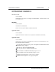
5–4 Dimensioning rules 5.1.1.2 Nortel Networks Confidential AGCH + PCH common channel The channel payload is largely induced by “paging” messages used for locating the MS with a view to setting up a call. The remaining load is taken up by resource allocation messages issued by the AGCH for location updating purposes, paging responses and calls emitted by MS onto the fixed network. The rule is to systematically reserve at least one access grant channel (AGCH).
Nortel Networks Confidential Dimensioning rules 5–5 Wiring rule: a PCM link enters via an even DTI board (2. n) and leaves via an odd DTI board (2.n + 1). TEI rule: from the first BTS to the last BTS chained, the TEI number assigned to each BTS must be increased by 1. Number of TCHs and secondary LAPD: 2 x number of TRXs + secondary LAPD number of PCMs connected to the BTS without taking into account redundant PCM links.
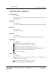
5–6 Dimensioning rules Nortel Networks Confidential Radio Interface BTS BTS BTS ÏÏ ÏÏ ÏÏ Ï Ï Ï Ï BTS ÏÏ ÏÏ ÏÏ Chain connection ÏÏ ÏÏ ÏÏ Star connection Abis Interface BSC BTS BTS ÏÏ ÏÏ ÏÏ ÏÏ ÏÏ ÏÏ BTS ÏÏ ÏÏ ÏÏ Loop connection BTS BTS ÏÏ Ï Figure 5–1 PE/DCL/DD/0063 411–9001–063 ÏÏ ÏÏ ÏÏ BTS Ï Ï Ï Hub and Spoke connection BTS ÏÏ ÏÏ ÏÏ Types of BTS connections Standard 12.
Nortel Networks Confidential 5.2 Dimensioning of the BTS 5.2.
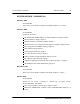
Dimensioning rules 5–8 5.2.2 Nortel Networks Confidential Dimensioning of radio and Abis interfaces Table 5–1 determines the number of traffic channels (TCH) required per cell, with an assumption of 25 mE/subscriber at peak time. The jam rate is 2% for the TCHs and 10–3 for SDCCH. Config. Standard cell Extended cell LAPD channels Voice time slot PCM No. Erlangs TCH Erlangs TCH O1 2.27 6 0.6 3 1 2 1 O2 8.20 14 2.23 6 1 4 1 O4 21.0 29 8.20 14 1 8 1 O8 48.
Nortel Networks Confidential Dimensioning rules 5.2.3 Dimensioning of DSC board (with BCF) 5.2.3.1 Design of DSC boards 5–9 The following table gives the number of DSC boards required according to the number of cells and the number of concentrated signaling links (without redundancy).
5–10 Dimensioning rules ÉÉÉÉÉÉÉÉÉÉÉÉÉÉÉÉÉÉÉÉ ÉÉÉÉÉÉÉÉÉÉÉÉÉÉÉÉÉÉÉÉ Frequency band Coupling system D Nortel Networks Confidential Configuration S8000I BTS S8000O BTS 1O1 to 1S222 GSM 900, GSM 1800 R–GSM, GSM 900, GSM 1800 GSM 1900, R–GSM 2S111_111 to 2S222_222 Dual band 900/1800 Dual band 900/1800 O2 S8002 BTS R–GSM D + CC8 2O16 to 3S888 GSM 1800 with CBCF module H2D 1O1_O1 to 1O4_O4 Dual band 900/1800 Dual band 900/1800 1O1 to 3S888 * GSM 900, GSM 1800 GSM 900, GSM 1800, GSM 1900 3
Wireless Service Provider Solutions S8000/S8002/S8006 BTS Reference Manual Copyright 1996–2000 Nortel Networks, All Rights Reserved NORTEL NETWORKS CONFIDENTIAL: The information contained in this document is the property of Nortel Networks.