Administering Avaya Video Conferencing Solution Advanced Topics 04-603308 Issue 2.1 Release 6.0.
© 2010 Avaya Inc. All Rights Reserved. Notice While reasonable efforts have been made to ensure that the information in this document is complete and accurate at the time of printing, Avaya assumes no liability for any errors. Avaya reserves the right to make changes and corrections to the information in this document without the obligation to notify any person or organization of such changes.
1-800-242-2121 in the United States. For additional support telephone numbers, see the Avaya Website: http://www.avaya.com/support.
Contents Chapter 1: Avaya Video Conferencing Solution . . . . . . . . . . . . . . 9 AVCS configurations . . . . . . . . . . . . . H.323-only video solution . . . . . . . . . SIP-only video solution . . . . . . . . . . Combined H.323 and SIP video solution . . . . . . . . . . . . . . . . . . . . . . . . . . . . . . . . . . . . . . . . . . . . . . . . . . . . . . . . . . . . . . . . . . . . . . . . . . . . . . . . . 10 10 11 12 Avaya AuraTM solution . . . . . . . . . .
Contents Administering Avaya 1000 series and Avaya one-X® Communicator video endpoints and users using System Manager . . . . . . . . . . . . . . . . . . . . . . . . . . 69 Avaya A175 Desktop Video Device . . . . . . . . . . . . . . . . . . . . . . . . 71 Administering and setting up video H.323 endpoints . . . . . . . . . . . . . . . . 74 Configuring a Direct Routing Gatekeeper . . . . . . . . . . . . . . . . . . . . 74 Configuring Video Trunks between two Communication Manager Systems .
Chapter 1: Avaya Video Conferencing Solution The Avaya Video Conferencing Solution (AVCS) enhances and extends the use of Avaya Aura™ Communication Manager, Avaya Aura™ Session Manager, and Avaya Aura™ System Manager as a SIP-based platform for video communications. Communication Manager, Release 6.0.x, is an H.323-to-SIP and a SIP-to-SIP video signaling gateway that supports single and mixed protocol video deployments.
Avaya Video Conferencing Solution AVCS configurations AVCS supports three configurations: H.323-only video solution, SIP-only video solution, and a combined H.323 and SIP video solution. H.323-only video solution The H.323-only solution consists of the following components: ● Communication Manager as gatekeeper ● Polycom CMA as gatekeeper ● Polycom RMX gateway ● Polycom VPB-E video border proxy ● Polycom, Tandberg, and Avaya H.323 endpoints In this solution, the H.
AVCS configurations Figure 1: H.
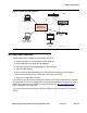
Avaya Video Conferencing Solution Figure 2: SIP-only video solution TM Avaya Aura Conferencing Polycom RMX Avaya Video Conferencing Manager TM Avaya Aura Core Session Manager System Manager Polycom HDX Communications Manager as FS or ES Avaya A175 Avaya One-X Communicator Avaya 1000-series (1010/1020 and 1030/104/1050) cycmasip LAO 111610 Combined H.323 and SIP video solution The combined H.
AVCS configurations ● Polycom, Tandberg, and Avaya SIP and H.323 endpoints. This solution allows multivendor video devices to operate with Avaya video devices. In this configuration, both H.323 and SIP devices connect through Session Manager, and Communication Manager must be configured as an evolution server. As with the H.323-only configuration, the Polycom RMX gateway connects through either Communication Manager or the Polycom CMA gatekeeper but not both. However, for Release 6.
Avaya Video Conferencing Solution Figure 3: Combined H.323 and SIP video solution TM Avaya Aura Avaya Video Conferencing Conferencing Manager System Manager Communications Manager as ES Avaya One-X Communicator (H.323) TM Avaya Aura Core Session Manager Polycom CMA Polycom VBP-E 6.1 y onl Avaya One-X Communicator (SIP) ly rR e fo .
Avaya AuraTM solution ● ● ● ● Avaya AuraTM Communication Manager administered as a feature server—provides Communication Manager features to SIP endpoints only. Avaya AuraTM Communication Manager administered as an evolution server—provides Communication Manager features to both SIP and non-SIP endpoints. Avaya AuraTM Presence—a service that conveys a person's ability and willingness to communicate across a set of services, such as telephony and instant messaging. SIP or H.
Avaya Video Conferencing Solution additional functionality, such as self registration for conferences, reseller and wholesaler users, and video conference calls. Avaya Aura™ Conferencing Manager Avaya Aura™ Video Conferencing Manager is a comprehensive management software solution for network administrators who manage video and voice communications systems in an IP environment.
Further information ● A network readiness test or network assessment was performed to ensure your network is capable of supporting bandwidth demands of video over IP. Avaya recommends implementing quality of service (QoS) across your network. ● Avaya licensing keys for RMX and HDX systems are installed. Also, ensure that administrators are familiar with ● System Manager domains, SIP entities, entity links, locations, routing, and dial patterns.
Avaya Video Conferencing Solution 18 Avaya Video Conferencing Solutions 6.0.1 Service Pack Issue 2.
Chapter 2: Design and deployment The chapter provides information that helps you design and deploy the Avaya Video Conferencing Solution. It covers managing your bandwidth to allow the quality of service needed to optimize video and the administration on Communication Manager and System Manager. Note: For the latest firmware video compatibility matrix, go to Avaya Support http://avaya.com/support and search for Firmware Video Compatibility Matrix.
Design and deployment ● 1.1 Mbps for 720p/60fps ● 1.7 Mbps for 1080p/30fps ● For content (that is, PC input) add ~1.0 Mbps (1040 and 1050 models only) ● For wideband audio add 80 kbps (includes overhead) Quality of Service Quality of Service (QOS) is the ability to provide different priority to different users and voice or data flows or to guarantee a certain level of performance to a data flow. It is not widely used for audio-only networks but is critical as multimedia is more widely deployed.
Managing video on your network For procedures for assigning bandwidths for SIP endpoints using Locations, see Setting up locations on page 32. For procedures for assigning bandwidths for H.323 endpoints using Network Regions, see Setting up bandwidth pools on page 34. This section addresses the additional partitioning methods organized by the type endpoints used in a typical enterprise: H.323 only, SIP only, or a combination of H.323 and SIP. H.323-only endpoints When the enterprise uses only H.
Design and deployment receive and deliver better quality and more reliable video during calls. However, they might not receive video on incoming calls received from video endpoints for normal users because ● No bandwidth is available ● No normal bandwidth is available even though priority bandwidth is available. The call is made by a normal video endpoint, and this endpoint did not have access to the priority bandwidth. Bandwidth pools For H.
Managing video on your network and multimedia calls. Audio comes from the normal video group. Bandwidth settings for video for all shows how you would configure the bandwidth for this example.
Design and deployment of the priority video bandwidth is used, it uses any available bandwidth in the normal video bandwidth group before using bandwidth from the audio bandwidth group. Example 5: Shared bandwidth for normal users - In this example, the following conditions exist: ● You want to share the normal video bandwidth group. ● You have no priority video users. Bandwidth settings for shared bandwidth for normal users shows how you would configure the bandwidth for this example.
Managing video on your network See Setting up bandwidth pools on page 34 for setting up bandwidth pools using Network Regions. SIP-only endpoints When the enterprise uses only SIP endpoints, bandwidth is divided up first by geographical location and then by audio or video. There are slight differences between Release 6.0 and 6.1 on how bandwidth is partitioned. If on Release 6.0, the video and audio pools cannot share bandwidth. Whatever bandwidth that’s assigned to those pools stays in those pools.
Design and deployment Figure 5: Bandwidth allocation for SIP-only solution, Release 6.0 Site 1 Site 2 Audio Pool Loc B bps Audio Pool Loc A 100 Mbps WAN 25 Mbps 5M 20 (Audio) Video Pool Mb ps Loc B (Video) cycmlsub LAO 111910 This enterprise has 125 Mbps of bandwidth available. Site 1, designated Location A, uses audio-only endpoints and is allocated 100 Mbps. Site 2, designated Location B, uses video desksets, a few video units in small conference rooms, and several audio endpoints.
Managing video on your network Site 2, designated Location B, uses video desksets and a few video units in small conference rooms, and several audio endpoints. Location B is allocated 25 Mbps with 5 Mbps supporting the audio pool and 20 Mbps supporting the video pool. For Release 6.1, audio and video endpoints share bandwidth within a location, so even though a certain amount of bandwidth is allocated to each pool, the audio pool can borrow bandwidth from the video pool if necessary.
Design and deployment See Setting up locations on page 32 for setting up bandwidth pools using Locations. Example 3: SIP audio and video - In this example, you want to allocate bandwidth for audio and video with most of the bandwidth going toward video. Bandwidth settings for SIP audio and video pools shows how you would configure the bandwidth for a single location.
Managing video on your network Site 1, designated Location A and Network Region 1, uses mostly SIP and some H.323 video endpoints within conference rooms and on desksets within the executive suites. They also use some SIP and H.323 video desksets throughout the building and audio endpoints as well. Location A is allocated 100 Mbps for the SIP endpoints, and Network Region 1 is allocated 50 Mbps for the H.323 endpoints. Site 2, designated Location B and Network Region 2, uses mostly H.
Design and deployment Example 1: Audio only for combination H.323 and SIP - In this example, your network has enough bandwidth to support audio only in one location. The SIP audio endpoints cannot share bandwidth with the H.323 audio endpoints. Calls made within a single location (intralocation calls) are counted against the total allocated bandwidth for the location. Bandwidth settings for audio only for both H.323 and SIP shows how you would configure the bandwidth for a single location.
Managing video on your network endpoints are further divided by normal and priority users. The SIP endpoints cannot share bandwidth with the H.323 endpoints. Calls made within a single location (intralocation calls) are counted against the total allocated bandwidth for the location. Bandwidth settings for audio and video for both H.323 and SIP shows how you would configure the bandwidth for a single location. Bandwidth settings for audio and video for both H.
Design and deployment Administration The following tasks provide procedures for setting up Locations within System Manager and administering Network Regions within Communication Manager. Setting up locations To set up locations within System Manager: 1. Log into the System Manager Web console. 2. Under Elements, select Routing. 3. Click Routing > Locations. 4. Click New to view the Location Details page. 5. Enter the location name in the Name field. 6. Enter notes about the location, if required. 7.
Administration Overall Managed Bandwidth section Name Description Managed Bandwidth Units Specifies the bandwidth unit for Overall Managed Bandwidth values. Total Bandwidth The total bandwidth available for use by any calls between this location and other locations. Any attempt to exceed this limit results in calls being alternate routed or denied. If no value is specified, the bandwidth limit is infinite.
Design and deployment Name Description Minimum Multimedia Bandwidth The minimum bandwidth specified per multimedia media stream that Session Manager uses while reducing the bandwidth request for a call to or from this location to enforce any bandwidth restriction. If a bandwidth restriction requires Session Manager to reduce a media stream below this level, the stream is removed from the call, possibly resulting in the entire call being blocked.
Administration Network Regions field descriptions codec-set Valid Entry Usage 1 to 7 pstn blank The codec set used between two regions. This field cannot be blank if this route through two regions is being used by some nonadjacent pair of regions. If the two regions are not connected at all, this field should be blank. direct-WAN Indicates whether the two regions (source and destination) are directly connected by a WAN link. The default value is enabled if a codec-set is administered.
Design and deployment Video (Norm) The amount of bandwidth to allocate for the normal video pool to each IP network region. Valid Entry Usage 0 to 9999 For units in Kbits 0 to 65 For units in Mbits blank If no allocation. This is the default setting. Video (Prio) The amount of bandwidth to allocate for the priority video pool to each IP network region. Valid Entry Usage 0 to 9999 For units in Kbits 0 to 65 For units in Mbits blank If no allocation. This is the default setting.
Call Admission Control Call Admission Control Overview Audio and multimedia calls require high bandwidth and low latency for best user experience. Call Admission Control (CAC), also known as Bandwidth Management, provides an efficient means to prevent degradation of quality by limiting the number of concurrent calls over limited bandwidth links. CAC enables in sustaining the network load imposed by the media traffic over the IP network.
Design and deployment 5. Specifies per-call bandwidth limits (as specified in Per-Call Bandwidth Parameters section), restricting the size of individual multimedia calls. Session Manager alters the SDP provided by call parties by enforcing the bandwidth limits as follows: ● Determines how much bandwidth to be reserved for each call and counts the determined value against the provisioned limit.
Call Admission Control Note: ● Calls terminated to non-SIP destinations (H.323 phones, non-SIP trunks) are counted by Communication Manager CAC for the appropriate Network Regions. ● All calls terminated to SIP destinations (SIP phones, SIP trunks on Session Manager) are counted by Session Manager CAC for the appropriate Locations. ● SIP trunks on Communication Manager that do not route to Session Manager (not a recommended configuration) are counted by Communication Manager.
Design and deployment Network and solution requirements This section provides a list of requirements for optimizing video within your network. Design and deploy a multimedia QoS policy. The Avaya one-X® Communicator, the AVCS 1000-series video endpoints, the Avaya A175 Desktop Video Device, and all Polycom conferencing devices support QoS for video. For more information, see the checklist in section 11.
Network and solution requirements Note: Note: Enter change ip-codec-set and enable the Allow Direct IP Multimedia field. In Communication Manager 6.0.x, there are two options: normal users and priority users. Allow reasonable inter-PBX network connectivity rates. Avaya recommends that inter-PBX network connectivity be less than 150 ms end-to-end one-way delay and less than 1% packet loss at all times. Otherwise, expect slower call establishment.
Design and deployment Allow reasonable VPN connection rates. Avaya recommends that for Avaya one-X® Communicator the VPN connection rates have a less than 150-ms one-way delay to Communication Manager, a packet loss less than 1%, and jitter less than 20 ms. The Avaya one-X® Communicator does not support automatic bit rate downgrades on packet loss feedback, nor does it perform ping tests for video assessment.
Feature Interactions and Limitations Feature Interactions and Limitations This section provides a list of possible interactions and limitations to consider. Call Recording, Whisper Page, or Service Observing is used on video calls. In this situation, expect audio-only calls unless the ad-hoc video conferencing feature is enabled. Each of these features counts as an audio-only participant in the call. See related issues below.
Design and deployment ● If you drop all but two of your video-enabled parties, video returns. No Bandwidth is available When all the available bandwidth has been used up by the endpoints on existing calls, the Avaya 1000 series video endpoints display a message No Bandwidth. Transfer to MGC/RMX is being used for ad-hoc video conferencing. In this situation, avoid scenarios where a user attempts to transfer to a meeting room where tandem Communication Manager systems link the user to the Polycom MGC/RMX.
Chapter 3: Administering Conferencing and Bridges This section of the guide explains how to set up Conferencing and Bridges. This section explains the administration of the following: 1. Configuring the S6800 bridge 2. Configuring Avaya Aura® Conferencing Configuring the Avaya Aura® Conferencing 6.0 Standard Edition In this section, you will: 1. Configure Conferencing for TLS or TCP so it will be able to communicate with Communication Manager. 2.
Administering Conferencing and Bridges ● MaxVideoChannelsAllowed The following is an example of a TLS configuration: # ip address of the server IPAddress=xxx.xxx.xxx.xxx #request we will be listening to #TLS MyListener=sip:6000@xxx.xxx.xxx.xxx:5061;transport=tls #TLS respContact=
Configuring the Avaya Aura® Conferencing 6.0 Standard Edition ● VideoSpeakersees Valid entries are current and previous. The default is previous. ● VideoSize Valid entries are CIF and QCIF. The default is CIF. ● VideoBandwidth Valid entries are 128, 192, 256, 384, 512, and 768 Kbit/s. The default is 384 Kbits/s. ● VideoMPI This parameter sets the minimum picture interval. Valid entries are 1 through 32. The default is 4. (VideoMPI=1 equals 30 fps.
Administering Conferencing and Bridges ● DIRECT to go directly into a pre-configured conference. Example: cbutil add 24049 0 301 1 n DIRECT -1 Adhoc in Avaya DNIS Grp ---------- Msg PS CP Function Line Name Company Name -------- ------- ----- ------ -------------- --------------- -------------------- 24047 0 247 1 N SCAN Schedule Avaya 24049 0 301 1 N DIRECT Adhoc Avaya 4. Using a text editor, open the file /usr/ipcb/config/telnumToURI.
Configuring the Avaya Aura® Conferencing 6.0 Standard Edition The following is an example of the system.
Administering Conferencing and Bridges Example of ConferenceProfiles.cfg Note: Note: The factory settings 1005 and 1006 should be the same on the Communication Manager system (Priority Factory number=1005, Standard Factory number=1006). c. On Conferencing, from sroot go to dcbmaint 116, select System Maintenance main menu > Administration menu > Conference Scheduler, and set the following parameters: ● Automatic Security Codes : 7 ● On-Demand Pct (%): as per customer requirement.
Configuring the Avaya Aura® Conferencing 6.0 Standard Edition Example of Configure Conference Scheduler Settings d. On Conferencing, configure the file usr/ipcb/config/UriToTelnum.tab for DNIS. This DNIS entry is used for creating an Ad-hoc conference. 24049 is DNIS for Ad-hoc. The same DNIS has to be in cbutil as DIRECT (Refer to the cbuilt section).See the following figure for an example of the UriToTelnum.tab file. Administering Avaya Video Conferencing Solution 6.0.1 Issue 2.
Administering Conferencing and Bridges Example of UriToTelnum.tab File 7. Schedule conferences on On Conferencing Configuring Resources On-Demand To enable FLEX conferences: a. Connect via ssh to the bridge. b. At the command prompt, enter featcfg +flex c. At the command prompt, enter dcbmaint 115 d. Select Administration Menu > Configure Scheduler e. Use the Page Down key to go to the second page. f. Set On-Demand Pct (%) as per user requirement (for example, 50).
Configuring the Avaya Aura® Conferencing 6.0 Standard Edition Scheduling Conferences There are two methods to schedule a conference on the bridge ● Method 1 a. Connect via ssh to the bridge. b. At the command prompt, enter dcbsched 116. c. Select Schedule Conference. d. Schedule your conference. e. When finished, press the Esc key. ● Method 2 Install the BridgeTalk application, which is a GUI scheduler that enables you to see your active conferences easily.
Administering Conferencing and Bridges Configuring Avaya Aura® Conferencing You must have administrator permission to edit the configuration and reboot the system for the changes to take effect. To configure the Avaya Aura® Conferencing: 1. Navigate to Configuration > Slot Configuration > Configure Video 2. From the Slot number for the card drop-down list box, select the MPC slot. 3. Set the following parameters in the Configure Video dialog box: ● Video MTU to 1492.
Configuring Avaya Aura® Conferencing Configuring Avaya Aura® Conferencing This section describes how to configure Conferencing. Checklist When setting up an Avaya Aura® Conferencing, you will need to know the following information: ● the IP codec sets you want to use ● the IP network regions you want use ● the Priority Factory Number and the Standard Factory Number to use in the Communication Manager system and the Conferencing.
Administering Conferencing and Bridges Verify Licensing Maximum Administered Ad-hoc Video Conferencing Ports. The maximum number of Ad-hoc video conferencing ports allowed is the number of video ports available for Ad-hoc use on the MCU(s). For example, if you have three MCUs, and each MCU has 16 ports available for Ad-hoc use, the maximum number of Ad-hoc video conferencing ports allowed is 48. In this example, the system can have: ● a maximum of 40 video-enabled Avaya IP Softphones.
Configuring Avaya Aura® Conferencing ● Units : NoLimit for each destination IP network region. You can set unlimited bandwidth or use the bandwidth management option by restricting the bandwidth. Repeat this procedure for each IP network region that will be used for video in this system.
Administering Conferencing and Bridges ● Outgoing Display :Y to display caller ID (from the Station screen) ● Service Type : tie ● Signaling Group : signaling group you created for the Conferencing. ● Number of Members : appropriate entry 58 Administering Avaya Video Conferencing Solution 6.0.1 Issue 2.
Administering Avaya Aura® Communication Manager for video endpoints This section of the guide explains the procedure to administer Communication Manager for all video endpoints. Communication Manager Global Administration 1. On SAT, enter change system-parameters customer-options, and set the following parameters: Maximum Video Capable H.323 Stations : 1x the number of single point Polycom VSX systems. Maximum Video Capable IP Softphones : equal to the number of video softphones.
Note: Note: The actual settings in this page and find out the customer’s reasons/requirements for these options to be disabled. Video endpoints do not need to be shuffled to resume video. Third-party endpoints will support basic call setup only. 4. On the IP Network Region screen, ensure all regions used by video endpoints are configured correctly. H.323 SECURITY PROFILES must contain any-auth for Polycom VSX/HDX series devices to authenticate.
Administering Avaya Aura® Communication Manager for video endpoints Review page 2 of all the codec-sets to be used by video stations and video trunks. Ensure Allow Direct-IP Multimedia is set to yes. Also ensure Maximum Call Rate for Direct-IP Multimedia set appropriately considering the codec-set is used for inter-region where there are bandwidth issues.? 10. Ensure Inter Region Video Bandwidth Management on the IP Network Region screen is used across WAN links.
Note: Note: For shared control when using video, the only option supported is via the server. Do not try using the via the phone (CTI) option. This is not supported, so expect undefined results. When using shared control with video, the network region used for Avaya IP Softphone must match the network region used by the IP set. 16. Ensure that Ad-hoc Video Conferencing is set to y for each class of user with Ad-hoc Video Conferencing privileges.
Administering and setting up video SIP endpoints Administering and setting up video SIP endpoints Global Administration 1. On SAT, enter display system-parameters customer-options and verify the following parameters: Note: ● ISDN PRI :Y ● IP Trunks : Y Note: You must log off and log back in to effect changes to System Parameters Customer-Options screen. 2.
2. On the ARS Digit Analysis Table screen, ensure that dialed strings of digits are interpreted correctly and the resulting calls are routed appropriately using the SIP trunks. Note: Note: You may not access a SIP trunk with a dialed TAC. If you use Avaya Distributed Office, you must administer this screen to use AAR. Avaya Distributed Office does not use ARS. 3. On the Dial Plan Analysis screen, translating the digits dialed by users, the summary of your dial plan must be available for reference. 4.
Administering and setting up video SIP endpoints proxy edge server. For external SIP calling, the domain name could be that of your SIP service provider. ● DTMF over IP : rtp-payload. ● SIP Session Establishment Timer : Avaya recommends 3 minutes. ● Enable Layer 3 Test : optional. The default is n. The value n uses the ping test and does not use the OPTIONS test. Enter Y to use the OPTIONS test instead of a ping. 2.
Administering SIP stations This procedure explains the procedure to set up stations on Communication Manager. 1. On SAT, enter add station n and set the following parameters: ● Type : 46n / 96n, where n is the number of your station type. For example, if you use 46n as the Type, the system generates minor alarms for these stations. You may ignore these alarms. However, if the Type is set to any of the DCP phone types, such as 6400 or 8400, undesirable interactions with the TTI and other features may occur.
Administering and setting up video SIP endpoints Administering Avaya 1000 series video endpoints using SAT This section describes the procedure to administer the Avaya 1000 series video endpoints using SAT. 1. On the Communication Manager SAT screen, enter change system parameters customer-options and set the following settings: ● Multimedia IP SIP Trunking : Y 2.
Administering Avaya 1000 series video endpoints using System Manager This section describes the procedure to administer the Avaya 1000 series video endpoints using System Manager. 1. To enable Multimedia IP SIP Trunking feature on Communication Manager System Management Interface, log in to the Communication Manager System Management Interface. Click Licensing > Administration and then navigate to the Feature Administration page. Here, ensure the Multimedia IP SIP Trunking feature is set to YES. 2.
Administering and setting up video SIP endpoints Administering Avaya 1000 series and Avaya one-X® Communicator video endpoints and users using System Manager This section describes how to use System Manager to create an endpoint template and how to add users using these templates. Creating a template for Avaya 1000 series and one-X® Communicator video endpoints and users using System Manager 1.
Adding users to Avaya 1000 series and one-X® Communicator video endpoints and users using System Manager 6. To create a New User Profile on System Manager, on the interface, click Users > Manage Users and then on New to open the New User Profile page.
Administering and setting up video SIP endpoints Avaya A175 Desktop Video Device This section of the guide explains how to set up and administer the Avaya A175. Pre-requisites 1. Know your telephone number. 2. Know the password for your telephone number. 3. Be connected to a network. 4. Know your Facebook login and password if you want to access Facebook from the Avaya A175 Desktop Video Device. 5.
6. In the Enter Security Question box, enter the security question that you want the Avaya A175 Desktop Video Device to ask you if you forget your unlock password. 7. In the Enter Answer box, enter the answer for your security question, and then click Next. 8. In the Audio panel, adjust the slider to set the ringer volume. Dragging the slider to the left decreases the ringer volume. Dragging the slider to the right increases the ringer volume. When finished adjusting the ringer volume, click Next. 9.
Administering and setting up video SIP endpoints ● In the Account options panel, verify your settings, and Click Next. ● If you want to provide a name for this account, enter the name in the Give this account a name box. ● In the Your name box, specify how you want your name to be displayed on outgoing messages from this email account, and then click Next. By default, the Avaya A175 Desktop Video Device will automatically sync with your Microsoft Exchange account.
Administering and setting up video H.323 endpoints This section describes the procedure for setting up and administration of H.323 endpoints. Configuring a Direct Routing Gatekeeper This section describes how to configure a direct routing gatekeepers such as SE200, PathNavigator and Polycom CMA.
Administering and setting up video H.323 endpoints On page 2 of the screen, set ● Allow Direct-IP Multimedia : Y ● Maximum Call Rate for Direct-IP Multimedia : This setting is the combined audio and video transmit rate or receive rate for non-priority (normal) video calls. You can use this setting to limit the amount of bandwidth used for normal video calls. For example, if you select 384 Kbits, a maximum of 384 Kbits will be used to transmit and to receive audio/video.
● Far-end Network Region : the appropriate IP network region. ● Direct IP-IP Audio Connections : Y ● IP Audio Hairpinning : N Adding an Outbound Trunk Group for the Gatekeeper To add an outbound trunk group for the system, enter add trunk-group n (where n is the chosen trunk group) and set the following parameters: ● Group Type : ISDN ● Carrier Medium : IP On page 5 of the Trunk Group screen add members to the trunk group.
Administering and setting up video H.323 endpoints ● RRQ Required : N ● Far-end Network Region : the appropriate IP network region ● Direct IP-IP Audio Connections : Y ● IP Audio Hairpinning : N Adding an Inbound Trunk Group for the Gatekeeper To add an inbound trunk group for the system, enter add trunk-group n (where n is the chosen trunk group) and set the following parameters: Group Type : ISDN Carrier Medium : IP. Go to page 5 of the Trunk Group screen and add members to the trunk group.
Example of Gatekeeper Sig Group display signaling-group 51 SIGNALING Group Number 51 Group Type h.323 Remote Office n Max number of NCA TSC 0 SBS n Max number of CA TSC: 0 IP Video y Priority Video y Trunk Group for NCA TSC Trunk Group for Channel Selection 51 TSC Supplementary Service Protocol a Network Call Transfer n T303 Timer(sec) 10 H.
Administering and setting up video H.323 endpoints DTMF over IP out-of-band Direct IP-IP Audio Connections y Link Loss Delay Timer(sec) 90 IP Audio Hairpinning n Enable Layer 3 Test n Interworking Message PROGress H.323 Station Outgoing Direct Media n DCP/Analog Bearer Capability 3.1kHz Setp Configuring Video Trunks between two Communication Manager Systems This section describes how to configure video trunks between two Communication Manager systems.
Adding a Signaling Group for the Video Trunk To add a signaling group for the video trunk, enter add signaling-group n (where n is the chosen signaling group) and set the following parameters: ● Group Type : H.
Administering and setting up video H.323 endpoints Creating a Route Pattern for the Video Trunk To create a route pattern that points to the trunk group, enter change route-pattern n (where n is the route pattern you want to use) and set the following parameters: ● Grp No : enter the number of the trunk group you created. Avaya one-X® Communicator Avaya one-X® Portal integration and video calls feature are installed by default. However, these are not enabled.
Note: Note: Avaya one-X® Communicator uses the same pool of video licenses counted by the Maximum Video Capable IP Softphones parameter. To provide video softphone capability, you must have at least this number of Avaya one-X® Communicator licenses. Page 10 of this screen displays the number of Avaya one-X® Communicator licenses you have. Setting Up Video Endpoints Perform this procedure if you want to allow priority video calling. 1.
Administering and setting up video H.323 endpoints ● whether the VSX/HDX system has the multipoint option or IMCU option. If so, you must combine the Polycom Software License for this capability with the “Avaya Option” Polycom Software License to create a single Key Code to input into the unit.
Note: Note: If the VSX system has the multipoint option or IMCU option, enter add station to add a second station for the Polycom system. The extension number should be one greater than the station added in the previous step. Set the following parameters: ● Type : H.323 ● Security Code : pin you will administer for the VSX/HDX. Ensure the security code is the same as the previous station. Each station configured for the multipoint device must use the same security code.
Administering and setting up video H.323 endpoints ● Note: the IP address of the C-LAN Note: Make sure you have the RMX Installation and Configuration guide available when you configure the RMX. Adding an Entry in the IP Node Names for the RMX System To add an entry in the IP Node Names screen for the RMX system, enter change node-names ip to access the IP Node Names screen. Set the following parameters: ● Name : enter a name for the RMX system.
● ARQ Required : Y ● Enable Layer 3 Test : N ● Far-end Node Name : the name entered for the RMX system. ● Far-end Listen Port : 1720 ● Far-end Network Region: 1720 ● Calls Share IP Signaling Connection : N ● Direct IP-IP Audio Connections : Y ● IP Audio Hairpinning : N Configuring Polycom MGC Series Video Conferencing Systems This section describes how to configure a Polycom MGC series video conferencing.The following procedure.
Administering and setting up video H.323 endpoints video conferencing ports allowed is 48. This is a license count that Avaya provides based on your stated needs. Licensing and administration are two different decisions on port counts.
● DTMF over IP : in-band ● Survivable COR : internal ● Survivable trunk dest : Y ● Authentication reqd : Y Configuring Polycom VBP-E To configure a Polycom VBP-E using Communication Manager complete the following procedure: 1. On SAT, enter change signalling group n (where n is the group number) and set the following parameters: ● IP Video : Y ● Near end listen port : 1720 ● Far end listen port : 1720 ● LRQ required : N ● RRQ required : N 2.
Chapter 4: Administering video endpoints This section describes the procedure to administer the actual endpoints to enable video conferencing. Administering video SIP endpoints Avaya 1000 series video endpoints Perform the following steps to configure all AVCS 1000 series video endpoints using the IR Remote Control. The endpoint GUI may also be used for configuring the endpoint using a web browser. 1. Log on to the video endpoint. The default password is 1234.
Administering video endpoints ● SIP Registrar : Enabled ● Registrar Hostname : Same as Proxy Hostname ● TCP : Enabled ● TCP signaling port : 5060 4. To confirm or verify if user registration is complete, under Communication click SIP and ensure the following. ● Registrar Status : Registered 5. To configure the AVCS 1000 series endpoints using a web browser, enter the IP address of the endpoint in the address bar and follow the steps as shown above.
● Avaya VirtualLink requires Adobe AIR 2.0 to communicate with Avaya 1010/1020. Adobe AIR 2.0 must be installed on the computer that is running Avaya VirtualLink. Browse to get.adobe.com/air to download the application. ● You can prepopulate video system entries in Avaya VirtualLink by editing the EndpointList.xml file that is included with the application. Your video system entries are copied during installation. With this method, PC users are not required to add systems individually.
Administering video endpoints on whether you selected H.323 or SIP protocol during installation. For SIP protocol enter the following information: ● Extension : enter your extension on the Avaya server ● Password : enter your password 2. To specify the IP address of your server, click Add below the Server List field. The Add Server dialog box appears. Set the following parameters: ● Proxy Server : enter the IP address of the proxy server. ● Port : enter the port number of the server.
● Connection Type : click the type of connection for your network. ● Jitter Buffer : click the size of your Jitter Buffer. Set your Jitter Buffer according to your network parameters and the packet losses. Avaya recommends you to set this option to Automatic. ● Move the Receive Gain slider to set the gain for incoming sound during a call. Avaya recommends you to set this option to 1.00. ● Move the Transmit Gain slider to set the gain for outgoing sound during a call.
Administering video endpoints Note: Note: If you specify multiple extension lengths, Avaya one-X® Communicator performs exact matches. For example, if you specify 3, 5, 7, Avaya one-X® Communicator treats three-digit numbers, five-digit numbers, and seven-digit numbers as internal extensions. In this example, if you dial a one-digit, two-digit, or four-digit number, Avaya one-X® Communicator does not recognize the numbers to be internal extensions.
● Max Entries : enter the maximum number of matching entries that you want Avaya one-X® Communicator to display. The default is 50. Select the Use Active Directory GSS Bind check box, if you want Avaya one-X® Communicator to use the current user’s login and password to bind with the Active Directory LDAP server. IM and Presence screen IM and Presence appears on the left pane only if you selected SIP protocol during this protocol.
Administering video endpoints Preferences screen 1. Click Preferences on the left pane of the General Settings window. The Preferences settings appear on the right pane of the General Settings window. 2. Select the Display alerts for incoming calls check box if you want Avaya one-X® Communicator to display alerts when you receive incoming calls. 3.
2. Enter change off-pbx-station mapping n (where n is the station number of device being used) and ensure all bridged call items are set to none. None is the default option. Set the following parameters: ● Station Extension : appropriate entry ● Application : appropriate entry ● Dial Prefix : appropriate entry ● Phone Number : appropriate entry ● Trunk Selection :appropriate entry ● Configuration Set : appropriate entry ● Call Limit : appropriate entry 3.
Administering video endpoints On the station screen, ensure the following settings: Note: ● Bridged Call Alerting : Y ● Restrict Last Appearance : N ● AUDIX Name : the name of the voice messaging system administered for this system ● Coverage after Forwarding : S, default for system ● Per Station CPN Send Calling Number : N ● Button Assignments : 1. Call Appr; 2. Call Appr Note: To support certain transfer and conference scenarios, the minimum number of call-appr buttons should be 3.
Administering H.323 video endpoints Administering H.323 video endpoints This section describes administration of video endpoints for H.323 protocol. Configuring Polycom VSX/HDX Endpoints: To configure the Polycom system install the Polycom system and connect it to your network. Upgrade the Polycom system software (if necessary) and using a web browser, access the Polycom home page for the unit, and select Admin Settings>Network>IP Network and follow the procedure below: 1. Select the Enable IP H.
Administering video endpoints Note: Note: Remote control can have its RF band customized if controlling more than one system. Remote control can also be used to switch display modes by holding down the power button. When finished, click the Update button. Repeat Steps 1 through 14 for each Polycom system. Configuring the Polycom RMX System 1. To configure the Polycom RMX system, install the RMX system and connect it to your network. Upgrade the Polycom system software (if necessary).
Administering H.323 video endpoints Configuring Polycom RMX H.323/SIP to H.320 Support – Incoming/outgoing ISDN Calls Provides interoperability with video endpoints on public ISDN communication services. PRI lines can be direct from the network or routed through the Communication Manager to share PRI resources. Communication Manager supports T1/E1 lines. To configure the Polycom RMX system, install the RMX system and connect it to your network. Upgrade the Polycom system software (if necessary). 1.
Administering video endpoints ● Conference Profile : Select the Profile to be used by the Entry Queue. ● ID : Enter a unique number identifying this conferencing entity for dial in. Default string length is 4 digits. ● Gateway Dial Out Protocols : enable all options, H.323, SIP, H.320, and PSTN.
Administering H.323 video endpoints Configuring Polycom VBP-E Support – Incoming/Outgoing External Video Calls Video calls coming from or going to a Polycom H.323 endpoint with internet access are facilitated through the Polycom RMX endpoint as a gateway call to SIP endpoints. In this manner, calls can achieve HD resolution with an AVCS SIP endpoint. In H.323 RMX can be bypassed for an HD call between two H.323 endpoints. To configure the Polycom VBP-E : 1.
Administering video endpoints 3. On the VBP-E administration page, navigate to Configuration Menu > VoIP ALG > H.323 > Neighboring. The Prefix routing table is displayed.
Administering H.323 video endpoints Configuring the Polycom MGC series To configure a Polycom MGC endpoint: 4. Install the MGC system and connect it to your network. Upgrade the Polycom system software (if necessary). 5. Access the Polycom home page for the unit, and select MCU Configuration > Network Services > IP > IP Default > Network Service Properties to create a new H.323 service. 6. On the Settings tab, set the following parameters: ● Protocol : H323.
Administering video endpoints Configuring the Tandberg MXP endpoint The Tandberg endpoints do not support Dynamic Host Conifguration Protocol (DHCP) Option 242. This option is required in a network if there are Avaya 9600 Series Telephones present and DHCP is utilized. The workaround is to statically configure the H.323 gatekeeper on the Tandberg endpoints. You must configure Tandberg endpoints using the Control Panel Menus or the Command Line Interface (CLI). If you are configuring the H.