Avaya 1100 Series Expansion Module — User Guide Avaya Business Communications Manager Document Status: Standard Document Number: NN40050-118 Document Version: 02.
© 2010 Avaya Inc. All Rights Reserved. Notices While reasonable efforts have been made to ensure that the information in this document is complete and accurate at the time of printing, Avaya assumes no liability for any errors. Avaya reserves the right to make changes and corrections to the information in this document without the obligation to notify any person or organization of such changes.
Task List 3 Task List Installing an expansion module .....................................................................................21 Installing a second or third expansion module ..............................................................22 Mounting the expansion module and phone on a wall ..................................................23 Adjusting the tilt base ....................................................................................................
Task List NN40050-118
Contents 5 Contents Contents . . . . . . . . . . . . . . . . . . . . . . . . . . . . . . . . . . . . . . . . . . . . . . . . . . . . . . 5 Regulatory and safety information. . . . . . . . . . . . . . . . . . . . . . . . . . . . . . . . . 7 Other . . . . . . . . . . . . . . . . . . . . . . . . . . . . . . . . . . . . . . . . . . . . . . . . . . . . . . . . . . . . . . . 8 Other . . . . . . . . . . . . . . . . . . . . . . . . . . . . . . . . . . . . . . . . . . . . . . . . . . . . . . . . . . . . . .
Contents NN40050-118
Regulatory and safety information This equipment has been tested and found to comply with the limits for a Class B digital device, pursuant to part 15 of the FCC Rules. These limits are designed to provide reasonable protection against harmful interference in a residential installation. This equipment generates, uses and can radiate radio frequency energy and, if not installed and used in accordance with the instructions, may cause harmful interference to radio communications.
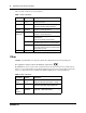
Regulatory and safety information Table 1 lists EMC compliance for various jurisdictions.
Regulatory and safety information 9 Table 2 EMC compliance Jurisdiction Standard European EN 55022 Community EN 55024 Description Class A Emissions: Information technology equipment - Radio disturbance Information technology equipment Immunity characteristics Limits and methods of measurement EN 61000-3-2 Limits for harmonic current emissions (equipment input current <= 16 A per phase) EN 61000-3-3 Limitation of voltage fluctuations and flicker in low-voltage supply systems for equipment with rated c
Regulatory and safety information • • • Operation is subject to the following two conditions: (1) this device may not cause interference, and (2) this device must accept any interference, including interference that may cause undesired operation of the device. Privacy of communications may not be ensured when using this telephone. To prevent radio interference to the licensed service, this device must be operated indoors only and should be kept away from windows to provide maximum shielding.
Regulatory and safety information 11 DenAn regulatory notice for Japan Avaya 1100 Series Expansion Module — User Guide
Regulatory and safety information NN40050-118
Customer service Visit the Avaya Web site to access the complete range of services and support that Avaya provides. Go to http://www.avaya.com or go to one of the pages listed in the following sections.
Customer service NN40050-118
Chapter 1 Getting started This section contains information on the following topics: • • • • “About this guide” on page 15 “Symbols and conventions used in this guide” on page 16 “Symbols and conventions used in this guide” on page 16 “Related publications” on page 16 About this guide This guide tells a hardware installer or an Avaya 1100 Series IP Deskphones user how to install and use Avaya 1100 Series Expansion Module.
Chapter 1 Getting started Symbols and conventions used in this guide These symbols are used to highlight critical information: Caution: Alerts you to conditions where you can damage the equipment. Danger: Alerts you to conditions where you can get an electrical shock. Warning: Alerts you to conditions where you can cause the system to fail or work improperly. Note: A Note alerts you to important information. Tip: Alerts you to additional information that can help you perform a task.
Chapter 2 Introduction This document describes the Expansion Module for IP Phone 1100 Series (expansion module) and how to use it with the compatible IP Phone 1100 series telephones.
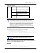
Chapter 2 Introduction Figure 1 Avaya 1140E IP Deskphone with expansion module Diagnostics LEDs Expansion module Line/feature keys LCD Line/feature key labels Services key Shift/Outbox key Display The expansion module is equipped with a graphical, pixel-based, gray-scale liquid crystal display (LCD). The LCD is located beside the 18 line/feature keys (see Figure 1 on page 18). Each of the 18 line/feature keys on the expansion module has a 10-character display label.
Chapter 2 Introduction 19 Setup and assembly The expansion module mounts on the right side of the IP Phone. Snap the expansion module into the accessory expansion module (AEM) on the back of the IP Phone. For installation procedures see Chapter 3, “Installing the expansion module,” on page 21. You can also wall mount the expansion module with IP Phone.
Chapter 2 Introduction Display Diagnostics menu Use the Up/Down navigation keys on your IP Phone to scroll the diagnostics menu and to access the following diagnostic operations for your IP Phone and expansion module. • • • Full Contrast LED Test Character Test Instructions are displayed in the LCDs of the IP Phone and the expansion module. The line/feature key display areas are blank.
Chapter 3 Installing the expansion module Complete the procedures in this chapter to install the expansion module for Avaya 1100 Series IP Deskphones. You must have an Avaya 1120E IP Deskphone and Avaya 1140E IP Deskphone in order to use Avaya 1100 Series Expansion Module. Installing an expansion module Caution: Damage to equipment To avoid damaging the equipment, remove the power (PeE cable or local power) from the IP Phone before you connect the expansion module.
Chapter 3 Installing the expansion module Installing a second or third expansion module Caution: Damage to equipment To avoid damaging the equipment, remove the power (PeE cable or local power) from the IP Phone before you connect the expansion module. You need a Phillips head screwdriver to complete this procedure. 1 Attach the second expansion module to the right side of the first expansion module. 2 Adjust the tilt of the IP Phone to a comfortable viewing angle.
Chapter 3 Installing the expansion module 23 Mounting the expansion module and phone on a wall You can wall-mount an IP Phone with an expansion module. You need the mounting template and the mounting bracket that came with the expansion module. You must attach the expansion module to your IP Phone before you mount them on the wall. Complete this procedure if you plan to mount the base station on a wall or ceiling. Skip this procedure if you plan to place the base station on a flat surface.
Chapter 3 Installing the expansion module NN40050-118
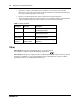
Chapter 4 Expansion module startup initialization Once you have installed and powered up the expansion module on the IP Phone, the expansion module initializes. Table 5 on page 25 describes the initialization process for the expansion module. Table 5 Initializing the expansion module Activity Description The expansion module performs a self-test The self-test confirms the operation of the local memory, CPU, and other circuitry f the expansion module.
Chapter 4 Expansion module startup initialization NN40050-118
Chapter 5 Using the handset This section describes how to use the expansion module to • • • • make calls put a call on hold program indicator keys use features There are many ways to place or answer a call, depending on how you program the indicator keys and the type of call you want to make. Making a call using a line key 1 Pick up the handset. 2 Press a key on the expansion module that is programmed as a Line key. You hear a dial tone.
Chapter 5 Using the handset Programming indicator keys You can program a programmable line or feature indicator key with a new number or feature. Programming external autodial 1 Press the Feature key. 2 Enter *1 using the telephone dial pad. 3 Press an indicator key. 4 Dial the external number. 5 Select OK to store the number. Programming names for external autodial on KEM 1 Press the Feature key. 2 Enter *1 using the telephone dial pad. 3 Press an indicator key.
Chapter 5 Using the handset 29 Programming internal autodial 1 Press the Feature key. 2 Enter *2 using the telephone dial pad. 3 Press an indicator key. 4 Dial the extension. 5 Select OK to store the number. Programming a feature 1 Press the Feature key. 2 Enter *3 using the dial pad. 3 Press an indicator key. 4 Select Feature. 5 Enter the feature code. 6 Select OK to store the feature code. Erasing a programmed indicator keys 1 Press the Feature key.