Avaya Solution & Interoperability Test Lab Configuring Avaya Communication Manager, Cisco 2811 Gatekeeper and Cisco CallManager to Control VoIP Calls between Avaya and Cisco Telephones - Issue 1.0 Abstract These Application Notes describe a configuration, including, Avaya Communication Manager, a Cisco 2811 Gatekeeper, and Cisco CallManager that was verified for a customer proof of concept request.
1. Introduction An H.323 gatekeeper can provide address translation and network access control services for H.323 terminals and gateways. These Application Notes present the configuration steps to allow Avaya Communication Manager to communicate with Cisco CallManager via a Cisco 2811 Gatekeeper. These Application Notes will cover the necessary configuration steps for Avaya Communication Manager, a Cisco 2811 Gatekeeper and Cisco CallManager.
Location A Location B Cisco 7960 IP Telephone 60.1.1.101 x61002 CISCO 796 IP PHONE 0 Avaya S8300 Server with G350 Media Gateway IP: 22.1.1.22 Avaya 2420 Digital Telephone x4501 1 2 3DE AB C F 4 5 6N GH JK M I L O 7 8 9 PQR TU WXY S V Z # 0 OPE R messagdirectori esi settin es servic es gs * MPLS WAN T1 Cisco CallManager 4.1 60.1.1.5 T1 Ethernet Ethernet Cisco Catalyst 3750 Zone: Remote Zone: Local CISCO 796 IP PHONE 0 Avaya 4600 IP Telephone X4550 22.1.1.
3. Avaya Communication Manager Configuration 3.1. Configuring Node Names on the Avaya Communication Manager This section presents configuration steps for node name to IP address mapping on Avaya Communication Manager. It is assumed that appropriate license and authentication files have been installed on the S8300 Server. It is also assumed that the network IP address on the S8300 Server has been configured to 22.1.1.22/24 and the IP address on the G350 GW has been configured to 22.1.1.23/24.
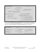
change ip-network-region 1 Page 1 of 19 IP NETWORK REGION Region: 1 Location: Name: Home Domain: Intra-region IP-IP Direct Audio: no Inter-region IP-IP Direct Audio: no IP Audio Hairpinning? n AUDIO PARAMETERS Codec Set: 1 UDP Port Min: 16384 UDP Port Max: 32767 DIFFSERV/TOS PARAMETERS Call Control PHB Value: 34 Audio PHB Value: 46 802.1P/Q PARAMETERS Call Control 802.1p Priority: 3 Audio 802.1p Priority: 6 H.323 IP ENDPOINTS H.
Use the command change ip-network-region 2 to specify the IP codec set to be used for network region 2 and the IP codec set used between network region 1 and region 2. Page 1 of 19 shows that codec set 2 is used for network region 2.
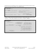
Use the command change ip-codec-set x (where x is the codec-set number) to configure IP codec(s). The following screens show the codec configuration. IP-codec-set 1 uses G.711MU and ip-codec-set 2 uses G.729. change ip-codec-set 1 Page 1 of 1 Page 1 of 1 IP Codec Set Codec Set: 1 Audio Codec 1: G.711MU 2: Silence Suppression n Frames Per Pkt 2 Packet Size(ms) 20 change ip-codec-set 2 IP Codec Set Codec Set: 2 Audio Codec 1: G.729 2: Silence Frames Packet Suppression Per Pkt Size(ms) n 2 20 3.3.
add signaling-group 20 Page 1 of 5 SIGNALING GROUP Group Number: 20 Group Type: Remote Office? SBS? IP Video? Trunk Group for Channel Selection: Supplementary Service Protocol: T303 Timer(sec): Near-end Node Name: procr Near-end Listen Port: 1719 LRQ Required? y RRQ Required? n Media Encryption? n DTMF over IP: out-of-band h.
Note that Codeset to Send Display must be configured to 0 in order for the Cisco GW to accept the Q.931 call setup message from the Avaya Media Gateway.
IP trunk member port values are initially configured to “ip” in the Port field. The system will then assign a value to the port as shown below. Note the IP trunk members are virtual ports. In the following screen, five members associated with signaling group 20 are configured. This means that the IP trunk group only supports five simultaneous VoIP calls. The sixth call will be blocked if there is no backup trunk available.
Separate signaling and trunk groups are required for Avaya Communication Manager to receive calls. When Avaya Communication Manager receives a call setup message from a Cisco CallManager via the Cisco 2811 Gatekeeper, Avaya Communication Manager will try to match it to a signaling group based on the remote GW’s IP address. The call will be denied if there is no match.
display trunk-group 21 Group Type: isdn Page TRUNK PARAMETERS Codeset to Send Display: 0 Disconnect Supervision - In? y Answer Supervision Timeout: 0 display trunk-group 21 TRUNK FEATURES ACA Assignment? n Used for DCS? n Suppress # Outpulsing? n GROUP MEMBER ASSIGNMENTS 1: 2: 3: 4: 5: 6: Port T00091 T00092 T00093 T00094 T00095 SZ; Reviewed: SPOC 8/10/2007 Name QSIG Value-Added? n Digital Loss Group: 18 Format: unk-pvt Insert: Out? n Page Measured: Internal Alert? Data Restriction? Send Name:
3.4. Configuring Dial Plan and Caller ID on Avaya Communication Manager Uniform Dialing Plan (UDP) and Automated Alternate Routing (AAR) are used for the call routing. The configurations in this section are for demonstration only. Use the command display system-parameters customer-options to verify that Uniform Dialing Plan is set to y.
Use the command change aar analysis 6 (“6” is the first dialed digit) to configure the dialed digits 61xxx to use aar and route pattern 20. change aar analysis 6 Page 1 of 2 AAR DIGIT ANALYSIS TABLE Percent Full: Dialed String Total Min Max 5 5 61 Route Pattern 20 Call Type aar Node Num 1 ANI Reqd n … Use the command change route-pattern 20 to set the trunk group 20 as a primary trunk group to carry the calls to 61xxx.
Use the command change private-numbering to change private format for the calling number. The configuration below will use the phone extension as the calling number. change private-numbering Page 1 of 1 NUMBERING - PRIVATE FORMAT Network Level: 0 Level 2 Code: Level 1 Code: PBX Identifier: Deleted Digits: 0 The command save translation must be entered to save the administration performed. 4. Cisco 2811 Gatekeeper and Cisco CallManager Configuration 4.1.
voice call carrier capacity active ! interface FastEthernet0/0 ip address 60.1.1.10 255.255.255.0 duplex auto speed auto ! ! ip classless ip route 0.0.0.0 0.0.0.0 60.1.1.2 Interface FastEthernet 0/0 configuration. gatekeeper zone local GateKeeper ABC.com 60.1.1.10 Enter Gatekeeper configuration Configure local zone GateKeeper with IP address 60.1.1.10. zone remote G350 ABC.com 22.1.1.22 1719 Configure remote zone G350 with IP address 22.1.1.22. Configure zone prefix for remote GK G350.
4.2. Configuring Cisco CallManager To use the Gatekeeper to control calls from the Cisco CallManager, the Cisco 2811 router must be added on the Cisco CallManager as a Gatekeeper. Configurations are shown below. 4.2.1. Add Gatekeeper Launch Cisco CallManager Administration Application and log in with proper user name and password. The display below shows the gatekeeper configuration. To add a gatekeeper, follow the following steps.
4.2.2. Add New Region Regions are used for codec selection. In these Application Notes, two regions are used. The default region is used for Location B and a new region, named Avaya, is created for Location A. To save bandwidth on WAN link, codec G.729 is used between these two regions. Intra-region calls will use codec G.711 ulaw. The following steps show how to create a new region on Cisco CallManager.
• • • Click System Æ Region Click Find and two regions are displayed Click the Region for avaya SZ; Reviewed: SPOC 8/10/2007 Solution & Interoperability Test Lab Application Notes ©2007 Avaya Inc. All Rights Reserved. 19 of 30 ACM-Cisco-CM-GK.
• • • Select G.711 for region avaya and G.729 for region default as shown below Click Update Click Restart Devices SZ; Reviewed: SPOC 8/10/2007 Solution & Interoperability Test Lab Application Notes ©2007 Avaya Inc. All Rights Reserved. 20 of 30 ACM-Cisco-CM-GK.
4.2.3. Add a New Device Pool There is a default device pool pre-defined on the Cisco CallManager. In these Application Notes, the Cisco CallManager will use this default device pool. A new device pool, named avaya, will be created for Avaya S8300 Server with G350 Media Gateway in Location A. The purpose of creating a new device pool is to use different regions defined in previous section to select different codec. The display below shows the device pool configuration utilized for these Application Notes.
• • • • • • • Enter avaya as Device Pool Name. Use drop-down menu to select avaya as Region. This will put this device pool into region avaya, which will use G.729 codec for calls to other region. Use drop-down menu to select 1-SampleAudioSource for Network Hold MOH Audio Source. Use drop-down menu to select 1-SampleAudioSource for User Hold MOH Audio Source. Leave other fields as default.
4.2.4. Add H.225 Trunk to the Gatekeeper A H.225 trunk is required for the Cisco CallManager to communicate with the Cisco 2811 Gatekeeper. The displays below show the configuration of adding a H.225 trunk to Cisco 2811 Gatekeeper. • • • • Click Device Æ Trunk Æ Add New Trunk Using the drop-down menu to select H.225 Trunk (Gatekeeper Controlled) Select H.255 as default for the Device Protocol Click Next SZ; Reviewed: SPOC 8/10/2007 Solution & Interoperability Test Lab Application Notes ©2007 Avaya Inc.
• • • • Enter Trunk-to-Gatekeeper as Device Name Select avaya for Device Pool Check the box for Wait for Far End H.245 Terminal Capacity Set Check the box for Enable Inbound FastStart SZ; Reviewed: SPOC 8/10/2007 Solution & Interoperability Test Lab Application Notes ©2007 Avaya Inc. All Rights Reserved. 24 of 30 ACM-Cisco-CM-GK.
• • • • • • Using the drop-down menu to select Gatekeeper IP address 60.1.1.10 for Gatekeeper Name Using the drop-down menu to select Gateway for Terminal Type Enter 1#* as Technology Prefix to match the gateway prefix configured on Cisco 2811 Gatekeeper. Leave other fields as default Click Update Click Reset Trunk SZ; Reviewed: SPOC 8/10/2007 Solution & Interoperability Test Lab Application Notes ©2007 Avaya Inc. All Rights Reserved. 25 of 30 ACM-Cisco-CM-GK.
4.2.5. Configure a Route Pattern Extension range 45xx is assigned to users at Location A. When users dial 45xx from the Location B, the Cisco CallManager knows how to route the calls to the Gatekeeper using the route pattern configured below. The call setup message will be carried out via the trunk selected in this route pattern. The display below shows the route pattern configuration utilized for these Application Notes. Follow the following steps to add a route pattern.
SZ; Reviewed: SPOC 8/10/2007 Solution & Interoperability Test Lab Application Notes ©2007 Avaya Inc. All Rights Reserved. 27 of 30 ACM-Cisco-CM-GK.
5. Verification Steps The following are the verification steps: • Use the commands status signaling-group 20 to check the signaling group is in service. status signaling-group 20 STATUS SIGNALING GROUP Group ID: Group Type: Signaling Type: Group State: • 20 h.323 facility associated signaling in-service Active NCA-TSC Count: 0 Active CA-TSC Count: 0 Make a call from extension 61000 (Cisco CallManager phone) to extension 4555 (Avaya IP telephone).
• Use the command status station 4555 from the SAT interface on Avaya Communication Manager to check the status of this Avaya IP telephone. As shown from page 4 below, this is a call using codec G.711MU from extension 4555 to S8300 Media Gateway VoIP engine (22.1.1.1) and the connection-type is ip-tdm. status station 4555 Page AUDIO CHANNEL Port: S00001 IP Other-end IP Addr :Port 22. 1. 1. 1 :2050 Switch Port G.
©2007 Avaya Inc. All Rights Reserved. Avaya and the Avaya Logo are trademarks of Avaya Inc. All trademarks identified by ® and ™ are registered trademarks or trademarks, respectively, of Avaya Inc. All other trademarks are the property of their respective owners. The information provided in these Application Notes is subject to change without notice.