Avaya Solution & Interoperability Test Lab Application Notes for Configuring Compressed Real-Time Protocol over Point-to-Point Protocol between Juniper Networks J4300 and M7i Routers to Support an Avaya IP Telephony Infrastructure – Issue 1.
1. Introduction Real-Time Protocol (RTP) packets generated by Voice over Internet Protocol (VoIP) telephony are typically small in size ranging in tens of bytes per packet. IP (20 bytes) and User Datagram Protocol (UDP) (8 bytes) headers are then added onto each packet before transmission. Because of the relative small packet size of RTP packets, the IP and UDP headers are all overhead.
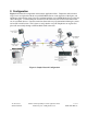
2. Configuration Figure 1 illustrates the configuration used in these Application Notes. Telephones with extension range 3xxxx are registered with the Avaya S8300 Media Server on the right side of the figure, and telephones with extension range 2xxxx are registered with the Avaya S8500 Media Server on the left side of the figure. A uniform dial plan and an H.323 IP trunk were used to route calls between the two Avaya Media Servers.
3. Equipment and Software Validated The following equipment and software/firmware were used for the sample configuration: Equipment Avaya S8300 Media Server with G350 Media Gateway Avaya S8500 Media Server Avaya G650 Media Gateway TN2312BP IPSI TN799DP C-LAN TN2302AP IP MedPro Analog telephone Avaya 6408D digital Telephone Avaya 4602SW IP Telephone (H.323) Avaya 4610SW IP Telephone (H.323) Avaya 4620SW IP Telephone (H.
4. Avaya Communication Manager There is no unique configuration required in Avaya Communication Manager to support cRTP or any feature mentioned in this document. For detailed information on the installation, maintenance, and configuration of Avaya Communication Manager, please consult references [1], [2], and [3]. Step Description Below is the output from the display ip-network-region command showing the 1. MEDIA PARAMETERS, and DIFFSERV/TOS PARAMETERS information configured in Avaya Communication Manager.
5. Configure the Juniper Networks Routers The following sections describe steps for configuration for the Juniper Networks routers in the sample configuration. Unless other wise specified, all routers configuration are based on Juniper Networks recommendation. See references [5], [6], [7], and [8]. 5.1. Configure the Juniper Networks J4300 router This section shows the necessary steps in configuring the J4300 router as shown in the sample network in Figure 1.
Step Description Configure the code-point-aliases and classifier for Avaya VoIP traffic. 3. • • • The alias helps identify the binary DSCP setting by giving it a name. The sample network uses the name “avaya-rtp” to denote DSCP binary bit 101110 for media traffic. This is equivalent to the decimal Audio PHB Value of 46 set in Avaya Communication Manager for RTP Media in Section 4, Step 1. The sample network uses the name “avaya-sig” to denote DSCP binary bit 100010 for signaling traffic.
Step Description Configure the scheduler to specify how much bandwidth to allocate for each type of 4. traffic queue. • The sample configuration defines a scheduler-maps called “voip” and assigns a name for each of the 4 queue types.
Step Description Assign the scheduler-map to each interface. 5. • Configure each interface with scheduler-map “voip” using the classifier defined above.
Step Description Configure the Ethernet and T1 interfaces. 6. • • Configure the Ethernet interface to use the scheduler. Assign an IP address to the interface. interop@J4300# interop@J4300# interop@J4300# interop@J4300# • • • Configure the logical interface for the WAN connection to use the scheduler. Assign an IP address to the interface. Specify the RTP traffic to be compressed. The sample configuration defines RTP traffic with port range 2048 to 3029 to be compressed.
5.2. Configure the Juniper Networks M7i router This section shows the necessary steps in configuring the M7i router as shown in the sample network in Figure 1. The following steps use the CLI. Step Description Connect to the M7i. Log in using the appropriate Login ID and Password. 1. login: Password: A prompt similar to the following will appear after successful log in. interop@M7I> 2. Enter configuration mode by typing in edit at the prompt.
Step Description Configure the code-point-aliases and classifier for Avaya VoIP traffic. 3. • • • The alias helps identify the binary DSCP setting by giving it a name. The sample network uses the name “avaya-rtp” to denote DSCP binary bit 101110 for media traffic. This is equivalent to the decimal Audio PHB Value of 46 set in Avaya Communication Manager for RTP Media in Section 4, Step 1. The sample network uses the name “avaya-sig” to denote DSCP binary bit 100010 for signaling traffic.
Step Description Configure the scheduler to specify how much bandwidth to allocate for each type of 4. traffic queue. • The sample configuration defines a scheduler-maps called “voip”, and assigns a name for each of the 4 queue types. interop@M7I# interop@M7I# interop@M7I# interop@M7I# interop@M7I# interop@M7I# interop@M7I# interop@M7I# • Use the scheduler to define the percentage of bandwidth allocation to each traffic queue type.
Step Description Assign the scheduler-map to each interface. 6. • Configure each interface with scheduler-map “voip” using the classifier defined above.
Step Description Configure the Ethernet and T1 interfaces. 7. • • Configure the Ethernet interface to use the scheduler. Assign an IP address to the interface. interop@M7I# interop@M7I# interop@M7I# interop@M7I# • • • Configure the logical interface for the WAN connection to use the scheduler. Assign an IP address to the interface. Specify the RTP traffic to be compressed. The sample configuration defines RTP traffic with port range 2048 to 3029 to be compressed.
6. Verification Steps The following steps may be used to verify the configuration. Step Description Verify network connectivity using “ping” from the PC. All network devices including 1. Avaya IP Telephones should be reachable. 2. Use the show services crtp flows command on the Juniper routers to verify traffic is being compressed. For an active phone call, there should be at least two flows displayed, one transmit and one receive. interop@J4300> show services crtp Interface: Interface: ls-0/0/0.
Step Description Bytes : 12011825 Queue: 3, Forwarding classes: network-control Queued: Packets : 9722 Bytes : 141217 4. 0 bps 0 pps 0 bps Use the show class-of-service forwarding-table command on the Juniper routers to verify the bandwidth allocation has been assigned to each interface. The following output has been abbreviated to only show the relevant interfaces. The allocation of bandwidth should match what is configured in Step 4 of Section 5.1 and 5.2.
Step Description PLP high: 1, PLP low: 1, PLP medium-high: 1, PLP medium-low: 1 Interface: t1-2/0/0, (Index: 139,, Map index: 2,, Map type: FINAL,, Num of queue s: 2): Index: 0 Entry 0 (Scheduler index: 17, Queue #: 0): Tx rate: 0 Kb (95%), Buffer size: 95 percent Priority low PLP high: 1, PLP low: 1, PLP medium-high: 1, PLP medium-low: 1 Entry 1 (Scheduler index: 19, Queue #: 3): Tx rate: 0 Kb (5%), Buffer size: 5 percent Priority low PLP high: 1, PLP low: 1, PLP medium-high: 1, PLP medium-low: 1 Interfac
Step Description Priority low PLP high: 1, PLP low: 1, PLP medium-high: 1, Entry 1 (Scheduler index: 62197, Queue #: 1): Tx rate: 0 Kb (80%), Buffer size: 80 percent Priority high PLP high: 1, PLP low: 1, PLP medium-high: 1, Entry 2 (Scheduler index: 62165, Queue #: 2): Tx rate: 0 Kb (5%), Buffer size: 5 percent Priority high PLP high: 1, PLP low: 1, PLP medium-high: 1, Entry 3 (Scheduler index: 45740, Queue #: 3): Tx rate: 0 Kb (5%), Buffer size: 5 percent Priority high PLP high: 1, PLP low: 1, PLP medium
8. Additional References Product documentation for Avaya products may be found at http://support.avaya.com [1] Administrator Guide for Avaya Communication Manager, Doc # 03-300509, Issue 1, June 2005 [2] Avaya Communication Manager Advanced Administration Quick Reference, Doc # 03-300364, Issue 2, June 2005 Release 3.
©2006 Avaya Inc. All Rights Reserved. Avaya and the Avaya Logo are trademarks of Avaya Inc. All trademarks identified by ® and ™ are registered trademarks or trademarks, respectively, of Avaya Inc. All other trademarks are the property of their respective owners. The information provided in these Application Notes is subject to change without notice.