Avaya Solution & Interoperability Test Lab Application Notes for Configuring Juniper Networks M7i and J4300 Routers to Support DHCP and a Compressed Real-Time Protocol enabled Point-to-Point Protocol Connection for an Avaya IP Telephony Infrastructure - Issue 1.0 Abstract These Application Notes describe the steps for configuring Juniper Networks M7i and J4300 routers to support an Avaya IP Telephony infrastructure consisting of Avaya Communication Manager and Avaya IP Telephones.
1. Introduction These Application Notes describe a solution for configuring the Juniper Networks M7i and J4300 routers to support an Avaya IP Telephony infrastructure. A Main site and a Branch site each have an Avaya Communication Manager server. The sites are connected together via a compressed RealTime Protocol (cRTP) enabled Point-to-Point Protocol (PPP) connection. An H.323 trunk is configured to route calls between the two sites. It is common to use the G.
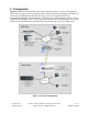
2. Configuration Figure 1 illustrates the configuration used in these Application Notes. All Avaya IP Telephones with extension range of 2xxxx are registered with Avaya Communication Manager at the Main site and all Avaya IP Telephones with extension range of 3xxxx are registered with Avaya Communication Manager at the Branch Site. An H.323 trunk, configured between the two Avaya Communication Manager servers, routes calls between the two sites.
3. Equipment and Software Validated The following equipment and software/firmware were used for the sample configuration provided: Equipment Avaya S8300 Media Server with G350 Media Gateway Avaya S8500 Media Server Avaya G650 Media Gateway TN2312BP IPSI TN799DP C-LAN TN2302AP IP MedPro Avaya 4602SW IP Telephone (H.323) Avaya 4610SW IP Telephone (H.323) Avaya 4620SW IP Telephone (H.
Step Description Configure the code-point-aliases and classifier for Avaya VoIP traffic. 3. • • • The alias helps identify the binary DSCP setting by giving it a name. The sample network uses the name “avaya-rtp” to denote DSCP binary bit 101110 for media traffic. This is equivalent to the decimal Audio PHB Value of 46 set in Avaya Communication Manager for RTP Media in Section 5, Step 8. The sample network uses the name “avaya-sig” to denote DSCP binary bit 100010 for signaling traffic.
Step Description Configure the scheduler to specify how much bandwidth to allocate for each type of 4. traffic queue. • The sample configuration defines scheduler-maps “voip” and assigns a name for each of the 4 queues types.
Step Description Assign the scheduler-map to each interface. 5. • Configure each interface with scheduler-map “voip” using the classifier defined above.
Step Description Configure the Ethernet and T1 interfaces. 6. • • Configure the Ethernet interface to use the scheduler. Assign an IP address to the interface. interop@J4300# interop@J4300# interop@J4300# interop@J4300# • • • Configure the logical interface for the WAN connection to use the scheduler. Assign an IP address to the interface. Specify the RTP traffic to be compressed. The sample configuration defines RTP traffic with port UDP range 2048 to 3029 to be compressed.
Step Description Configure the DHCP Server. The network was configured with 2 pools of IP addresses 8. with each pool serving out IP addresses from x.y.z.128 to x.y.z.191. DHCP option 176 directs Avaya IP Telephones from each site to their respective Avaya Media Server and port. interop@J4300# interop@J4300# interop@J4300# interop@J4300# interop@J4300# interop@J4300# interop@J4300# interop@J4300# interop@J4300# 9. edit system services dhcp pool 172.28.20.0/24 set address-range low 172.28.20.128 high 172.
Step Description Configure the code-point-aliases and classifier for Avaya VoIP traffic. 3. • • • The alias helps identify the binary DSCP setting by giving it a name. The sample network uses the name “avaya-rtp” to denote DSCP binary bit 101110 for media traffic. This is equivalent to the decimal Audio PHB Value of 46 set in Avaya Communication Manager for RTP Media in Section 5, Step 8. The sample network uses the name “avaya-sig” to denote DSCP binary bit 100010 for signaling traffic.
Step Description Configure the scheduler to specify how much bandwidth to allocate for each type of 4. traffic queue. • The sample configuration defines scheduler-maps “voip” and assigns a name for each of the 4 queue types. interop@M7I# interop@M7I# interop@M7I# interop@M7I# interop@M7I# interop@M7I# interop@M7I# interop@M7I# • Use the scheduler to define the percentage of bandwidth allocation to each traffic queue type.
Step Description Assign the scheduler-map to each interface. 6. • Configure each interface with scheduler-map “voip” using the classifier defined above.
Step Description Configure the Ethernet and T1 interfaces. 7. • • Configure the Ethernet interface to use the scheduler. Assign an IP address to the interface. interop@M7I# interop@M7I# interop@M7I# interop@M7I# • • • Configure the logical interface for the WAN connection to use the scheduler. Assign an IP address to the interface. Specify the RTP traffic to be compressed. The sample configuration defines RTP traffic with port range 2048 to 3029 to be compressed.
Step 12. Save the changes. Description interop@M7i # commit 5. Configure Avaya Communication Manager This section shows the necessary steps in configuring Avaya Communication Manager. For detailed information on the installation, maintenance, and configuration of Avaya Communication Manager, please consult reference [1], [2], [3], and [4]. The following steps describe the configuration of Avaya Communication Manager at the Main site.
Step Description change station 22022 Page 2 of 4 STATION FEATURE OPTIONS LWC Reception: LWC Activation? LWC Log External Calls? CDR Privacy? Redirect Notification? Per Button Ring Control? Bridged Call Alerting? Active Station Ringing: spe y n n y n y single H.320 Conversion? n Service Link Mode: as-needed Multimedia Mode: enhanced MWI Served User Type: AUDIX Name: Emergency Location Ext: 22022 2.
Step Description Configure a signaling group for the H.323 trunk between the Avaya Communication 3. Manager at the Main and Branch Site. Make sure the following fields are configured. Group Type: h.323 Trunk Group for Channel Selection: 1 (Signaling type used) (This value needs to be completed after Step 4 below has been completed) Near-end Node Name: clan (This is the clan name defined in Step 2) Near-end Listen Port: 1720 (Default port number for H.
Step Description Configure an H.323 trunk group. Use the add trunk-group command to create a new 4. trunk group. Group Type: isdn TAC: 101 Carrier Medium: H.323 Member Assignment Method: auto Signaling Group: 1 Number of Members: 50 (User assigned) (Type of trunk) (Signaling group number created in Step 3) (Number of members for the trunk group used for this sample network) add trunk-group 1 Page 1 of 21 TRUNK GROUP Group Number: Group Name: Direction: Dial Access? Queue Length: Service Type: 5.
Step Description display system-parameters customer-options OPTIONAL FEATURES Abbreviated Dialing Enhanced List? Access Security Gateway (ASG)? Analog Trunk Incoming Call ID? A/D Grp/Sys List Dialing Start at 01? Answer Supervision by Call Classifier? ARS? ARS/AAR Partitioning? ARS/AAR Dialing without FAC? ASAI Link Core Capabilities? ASAI Link Plus Capabilities? Async. Transfer Mode (ATM) PNC? Async. Transfer Mode (ATM) Trunking? ATM WAN Spare Processor? ATMS? Attendant Vectoring? 6.
Step Description Configure the IP network region using the change ip-network-region command. Note 8. the values for UDP Port Min, UDP Port Max, Call Control PHB Value and Audio PHB Value. These values are needed to configure the cRTP and QoS parameter on the routers. The IP NETWORK REGION form also specifies the codec set that will be used. All intra-region calls are configured to use the default ip-network region of 1 with the same value for parameters mentioned above.
Step Description Configure the appropriate audio codec using the change ip-codec-set command. The 9. following shows ip-codec-set 2 using G.729B. The G.711MU codec was also verified during the compliance testing. Media encryption was set for both aes and none to ensure interoperability with AES capable endpoints. change ip-codec-set 2 Page 1 of 2 IP Codec Set Codec Set: 2 Audio Codec 1: G.
6.1. General Test Approach Quality of Service was verified by injecting simulated data traffic into the network using a traffic generator while calls were being established and maintained using the Avaya IP Telephones. The J4300 router was configured to perform as a DHCP Server to test DHCP option 176 used by the Avaya IP Telephones. DTMF detection was tested using the Intuity AUDIX Voice Mail system configured in the S8300 Media Server.
10. Additional References Product documentation for Avaya products may be found at http://support.avaya.com [1] Administrator Guide for Avaya Communication Manager, Doc # 03-300509, Issue 2.1, May 2006 [2] Avaya Communication Manager Advanced Administration Quick Reference, Doc # 03-300364, Issue 2, June 2005 Release 3.
©2006 Avaya Inc. All Rights Reserved. Avaya and the Avaya Logo are trademarks of Avaya Inc. All trademarks identified by ® and ™ are registered trademarks or trademarks, respectively, of Avaya Inc. All other trademarks are the property of their respective owners. The information provided in these Application Notes is subject to change without notice.