Avaya Solution & Interoperability Test Lab Configuring Juniper Networks J4300 and Cisco 1841 Routers to use compressed Real Time Protocol over Point-to-Point Protocol to Support an Avaya IP Telephony Infrastructure – Issue 1.0 Abstract These Application Notes describe the steps for configuring Juniper Networks J4300 and Cisco Systems 1841 routers to use compressed RTP (cRTP) over a Point-to-Point Protocol (PPP) connection to support an Avaya IP Telephony infrastructure.
1. Introduction RTP packets generated by Voice over IP (VoIP) telephony are typically small in size ranging in tens of bytes per packet. Various headers such as IP (20 bytes) and UDP (8 bytes) are then added onto each packet before transmission. Because of the relative small packet size of RTP packet, the IP and UDP headers compose a large percentage of overhead in each frame.
2. Configuration Telephones with the extension range of 3xxxx are registered with the Avaya S8300 Media Server on the right side of the figure, and telephones with extension range of 2xxxx are registered with Avaya S8500 Media Server on the left side of the figure. A uniform dial plan and an H.323 IP trunk was used to route calls between the two Avaya Media Servers. IP addresses for all the devices are statically administered.
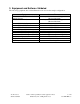
3. Equipment and Software Validated The following equipment and software/firmware were used for the sample configuration: Equipment Avaya S8300 Media Server with G350 Media Gateway Avaya S8500 Media Server Avaya G650 Media Gateway TN2312BP IPSI TN799DP C-LAN TN2302AP IP MedPro Avaya 4602SW IP Telephone (H.323) Avaya 4610SW IP Telephone (H.323) Avaya 4620SW IP Telephone (H.
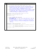
4. Avaya Communication Manager There is no unique configuration required in Avaya Communication Manager to support compressed RTP (cRTP) or any feature(s) mentioned in this document. For detailed information on the Installation, Maintenance, and Configuration of Avaya Communication Manager, please consult reference [5], [2], and [3]. Step Description Below is the output from display ip-network-region from the SAT terminal of Avaya 1. Communication Manager.
5. Configure the Networks Routers The following sections describe steps for configuring the Juniper Networks J4300 and Cisco Systems 1841 routers in the sample configuration. 5.1. Configure the Juniper Networks J4300 router. This section shows the necessary steps in configuring the Juniper Networks J4300 router as shown in the sample network. The following steps use the Command Line Interface (CLI) of the J4300 router.
Step Description Configure the code-point-aliases and classifier for Avaya VoIP traffic. 3. • • • The alias helps identify the binary DSCP setting by giving it a name. The sample network uses the name “avaya-rtp” to denote the dscp binary bit 101110 for media traffic. This is equivalent to the decimal vale of 46 set in Avaya Communication Manager for RTP Media in Section 4, Step 1. The sample network uses the name “avaya-sig” to denote dscp binary bit 100010 for signaling traffic.
Step Description Configure the scheduler to specify how much bandwidth to allocate for each type of 4. traffic queue. • The sample configuration defines a scheduler-maps called “voip”, and assign a name for each of the 4 queues types.
Step Description Assign the scheduler-map to each interface. 5. • Configure each interface with scheduler-map voip using the classifier defined above.
Step Description Configure the Ethernet and T1 interfaces. 6. • • Configure the Ethernet interface to use the scheduler. Assign an IP address to the interface. interop@J4300# interop@J4300# interop@J4300# interop@J4300# • • • Configure the logical interface for the WAN connection to use the scheduler. Assign an IP address to the interface. Specify the RTP traffic to be compressed. The sample configuration defines RTP traffic with port UDP range 2048 to 3029 to be compressed.
5.2. Configure the Cisco System 1841 router This section shows the necessary steps in configuring the Cisco 1841 router as shown in the sample network. The following steps use the Command Line Interface (CLI) of the Cisco 1841 router. Step Description Connect to the Cisco 1841 router. Log in using the appropriate Password. Enter into 1. enable mode using the appropriate enabled password.
Step Description Configure a class-map to define VoIP traffic. 2. • • The sample configuration uses the dscp value of the VoIP packet to define two class-map. One called “avaya-rtp”, and the other “avaya-sig”. Use the DSCP equivalent value set in Section 4, Step 1.
Step Description Define a policy-map to perform bandwidth allocation. The sample network defined a 3. policy-map called avaya-voip with 5% bandwidth allocated for signaling, 70% bandwidth allocated for RTP, and the remaining bandwidth for the rest of the traffic. 70% is the maximum bandwidth allocation that can be defined for a particular type of traffic in the Cisco 1841 router. • Compress RTP must be enabled using a policy map.
6. Verification Steps The following steps may be used to verify the configuration. Step Description Verify network connectivity using “ping” from the PC. All network devices including 1. Avaya IP Telephones should be reachable including network devices across the WAN connection. 2. 3. Place calls between Avaya IP Telephones across the two IP networks. Verify calls can be established and maintained.
Step Description Packets : 46978 Bytes : 2361646 Tail-dropped packets : 0 RED-dropped packets : 0 Low : 0 Medium-low : 0 Medium-high : 0 High : 0 RED-dropped bytes : 0 Low : 0 Medium-low : 0 Medium-high : 0 High : 0 Queue: 2, Forwarding classes: assured-forwarding Queued: Packets : 217241 Bytes : 12011825 Transmitted: Packets : 217241 Bytes : 12011825 Tail-dropped packets : 0 RED-dropped packets : 0 Low : 0 Medium-low : 0 Medium-high : 0 High : 0 RED-dropped bytes : 0 Low : 0 Medium-low : 0 Medium-high : 0
Step Description interop@J4300> show class-of-service forwarding-table Classifier table index: 12, # entries: 8, Table type: IPv4 precedence Entry # Code point Queue # PLP 0 000 0 0 1 001 0 1 2 010 0 0 3 011 0 1 4 100 0 0 5 101 0 1 6 110 3 0 7 111 3 1 Classifier table index: 6440, # entries: 2, Table type: DSCP Entry # Code point Queue # PLP 0 100010 2 0 1 101110 1 0 Table Index/ Interface Index Q num Table type sp-0/0/0.16383 66 12 IPv4 precedence ls-0/0/0.0 67 6440 DSCP fe-0/0/0.
Step Description Num of queues: 4): Index: 0 Entry 0 (Scheduler index: 13005, Queue #: 0): Tx rate: 0 Kb (10%), Buffer size: 10 percent Priority low PLP high: 1, PLP low: 1, PLP medium-high: 1, Entry 1 (Scheduler index: 62197, Queue #: 1): Tx rate: 0 Kb (80%), Buffer size: 80 percent Priority high PLP high: 1, PLP low: 1, PLP medium-high: 1, Entry 2 (Scheduler index: 62165, Queue #: 2): Tx rate: 0 Kb (5%), Buffer size: 5 percent Priority high PLP high: 1, PLP low: 1, PLP medium-high: 1, Entry 3 (Scheduler
Step Description From the Cisco 1841 router. Use the show policy-map interface s0/0/0 output to 6. display the interface statistics and ensure that the policy-map is configured correctly. The bandwidth allocation of bandwidth should match what is configured in Step 3 of Section 5.2.
7. Conclusion These Application Notes have described the administration steps required to configure RTP header compression (cRTP) to interoperate between a Juniper Networks J4300 and a Cisco Systems 1841 router over a Point-to-Point Protocol (PPP) connection to support the Avaya IP Telephony infrastructure. Quality of Service was implemented by the use of DSCP information for traffic priority queue assignment, and the use of bandwidth allocation on all the interfaces.
©2006 Avaya Inc. All Rights Reserved. Avaya and the Avaya Logo are trademarks of Avaya Inc. All trademarks identified by ® and ™ are registered trademarks or trademarks, respectively, of Avaya Inc. All other trademarks are the property of their respective owners. The information provided in these Application Notes is subject to change without notice.