56K/64K DSU/CSU Adapter Module Supplement Part No. 301271-A Rev.
4401 Great America Parkway Santa Clara, CA 95054 8 Federal Street Billerica, MA 01821 Copyright © 1998 Bay Networks, Inc. All rights reserved. Printed in the USA. August 1998. The information in this document is subject to change without notice. The statements, configurations, technical data, and recommendations in this document are believed to be accurate and reliable, but are presented without express or implied warranty.
Japan/Nippon Requirements Only Voluntary Control Council for Interference (VCCI) Statement Voluntary Control Council for Interference (VCCI) Statement This is a Class A product based on the standard of the Voluntary Control Council for Interference by Information Technology Equipment (VCCI). If this equipment is used in a domestic environment, radio disturbance may arise. When such trouble occurs, the user may be required to take corrective actions.
that the sum of the Ringer Equivalence Numbers of all the devices does not exceed 5. The REN is located on the “FCC Rules Part 68” label located on the bracket of the module, or on the back of the unit. Canada CS-03 -- Règles et règlements Avis: L'étiquette d'Industrie Canada identifie le matériel homologué.
Using the 56/64K DSU/CSU Adapter Module This document supplements the following guides: • Installing an Adapter Module in a BayStack AN or ANH Router • Installing and Operating BayStack ARN Routers (Chapter 4, “Installing a WAN Adapter Module”) Follow the hardware installation steps in the guide for your router, referring to this document for information specific to the 56/64K DSU/CSU adapter module.
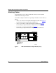
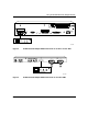
56K/64K DSU/CSU Adapter Module Supplement Attaching Cables Connect the Telco service cable to the RJ-48C connector on the installed 56/64K DSU/CSU adapter module. You install the adapter module in an open adapter module slot on the router, as follows: • ARN -- one of the two front-panel WAN adapter module slots (Figure 1). See Installing and Operating BayStack ARN Routers. • AN or 12-port ANH -- the back-panel adapter module slot (Figure 2).
Using the 56/64K DSU/CSU Adapter Module UL UL XCVR UTP TX RX CL CO M 2 CONSOLE COM 1 100-240V 50-60 Hz 1.0-0.5A RST RLSD1 RLSD2 DDS 56K/64K DSU/CSU Tx CD Rx Test Complies with FCC Rules Part 66 Reg. Number 4P8USA-24230-DE-N 56/64K DSU/CSU AN0136B Figure 2. 56/64K DSU/CSU Adapter Module Connector on an AN or 12-Port ANH COM 2 COM 1 COM 3/Expansion DDS 56K/64K DSU/CSU Tx CD Rx Test Complies with FCC Rules Part 66 Reg. Number 4P8USA-24230-DE-N 56/64K DSU/CSU AN0140B Figure 3.
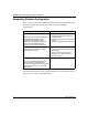
56K/64K DSU/CSU Adapter Module Supplement Completing Software Configuration Once you have successfully installed the adapter module, complete the following software configuration tasks using instructions found in your BayRS documentation: Configuration Task Location of Instructions Connect the ARN to the network.
Using the 56/64K DSU/CSU Adapter Module Interpreting LEDs The 56/64K DSU/CSU LEDs are identical in label, color, and function on each platform. They will blink on and off during diagnostic testing, but they will not stay on to indicate data transfer until you have configured and enabled software services. Table 2 describes the function of each 56/64K DSU/CSU LED. Table 2. 301271-A Rev.