
User's Guide
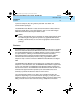
Table Of Contents
- Table of Contents
- About This Document
- 1. Introduction
- 2. Installation
- 3. Configuration and Operation
- 4. Troubleshooting
- A. AT Command Set
- B. Dial Modifiers
- C. S-Registers
- D. Isolating Problems Using Loopback Data Tests
- E. Quick-Reference Summaries
- Glossary
- Index
8400B Plus Data Module User’s Guide
555-020-709
Issue 2
November 1996
Introduction
1-4
Physical Description
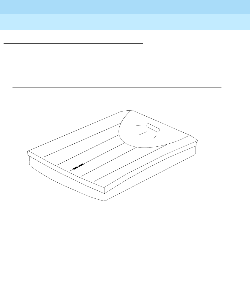
Front Panel
The front panel of the 8400B Plus Data Module is shown in Figure 1-1. One red
light emitting diode (LED) and one green LED on the front panel indicate the
status of the set during normal operation, and the result of self-tests when
initially powered.
Figure 1-1. Front Panel of the 8400B Plus Data Module
020709_2.book Page 4 Friday, April 23, 1999 5:39 AM