
User's Guide

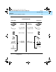
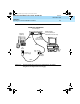
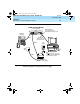
Table Of Contents
- Table of Contents
- About This Document
- 1. Introduction
- 2. Installation
- 3. Configuration and Operation
- 4. Troubleshooting
- A. AT Command Set
- B. Dial Modifiers
- C. S-Registers
- D. Isolating Problems Using Loopback Data Tests
- E. Quick-Reference Summaries
- Glossary
- Index

8400B Plus Data Module User’s Guide
555-020-709
Issue 2
November 1996
Introduction
1-6
Physical Description
_
Table 1-1. Rear Panel Connector Descriptions
Connector Description
PHONE This connector accepts one end of the D8W telephone line
cord used to connect a two-wire voice terminal to the
8400B Plus Data Module.
LINE/
POWER
This connector accepts one end of the D8W telephone
cord that connects between the 8400B Plus Data Module
and either:
■ a PBX wall jack already powered by a closet
supply, or
■ a power supply, which is connected to the PBX
wall jack.
EIA
CONNECTOR
INTERFACE
This unlabeled connector provides an interface between
the 8400B Plus Data Module and the terminal device.
■ If the communications port on the terminal
device is a 9-pin interface, use a cord with DB9
male connectors on each end to connect the
Data Module to the terminal device.
■ If the communications port on the terminal
device is a 25-pin interface, use a 25-pin
EIA-232-D cord, plus the supplied
M9/F25 Adapter to connect the Data Module to
the terminal device.
020709_2.book Page 6 Friday, April 23, 1999 5:39 AM