
User's Guide
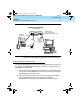
Table Of Contents
- Table of Contents
- About This Document
- 1. Introduction
- 2. Installation
- 3. Configuration and Operation
- 4. Troubleshooting
- A. AT Command Set
- B. Dial Modifiers
- C. S-Registers
- D. Isolating Problems Using Loopback Data Tests
- E. Quick-Reference Summaries
- Glossary
- Index
8400B Plus Data Module User’s Guide
555-020-709
Issue 2
November 1996
Installation
2-8
Hardware Installation
The most common EIA-232-D Connector cords are supplied with a male
connector at both ends. If you have this type of cord and the EIA-232-D port on
your terminal device is a male connector, you can use an adapter commonly
referred to as a “gender changer.” Otherwise, obtain an EIA Connector cord that
has the appropriate gender connector at each end to fit your application needs.
Selecting DCP Cords
One or more 7-foot D8W cords are supplied with your 8400B Plus Data Module.
Use the supplied cord, or obtain the appropriate length D8W telephone cord. If
you are using the
With Telephone
option (see ‘‘With Telephone’’ on page 2-12),
you will need the D8W telephone cord (already supplied with your telephone) to
connect between the 8400B Plus Data Module and your telephone.
Hardware Installation
This section outlines procedures for connecting the EIA Connector cord and
M9/F25 Adapter, installing the power supply, and connecting the D8W
telephone cord(s).
!
CAUTION:
To avoid possible shock hazards and damage to the equipment, you
should perform the installation steps in the order given.
Connecting the 8400B Plus Data Module to the
Te r mi n a l
Use the EIA Connector cord and, if necessary, the M9/F25 Adapter to connect
the 8400B Plus Data Module to the terminal device.
1. Connect one end of the Connector cord into the communications port on
the terminal device. Tighten all retaining screws.
020709_2.book Page 8 Friday, April 23, 1999 5:39 AM