
User's Guide
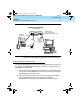
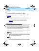
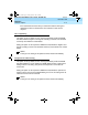
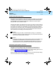
Table Of Contents
- Table of Contents
- About This Document
- 1. Introduction
- 2. Installation
- 3. Configuration and Operation
- 4. Troubleshooting
- A. AT Command Set
- B. Dial Modifiers
- C. S-Registers
- D. Isolating Problems Using Loopback Data Tests
- E. Quick-Reference Summaries
- Glossary
- Index

8400B Plus Data Module User’s Guide
555-020-709
Issue 2
November 1996
Installation
2-10
Hardware Installation
2. If you are installing the US Configuration, and using the separate power
supply provided with your 8400B Plus Data Module:
a. Plug the 400B2 Adapter into the PBX wall jack.
b. Plug the remaining end of the first D8W telephone cord into the
bottom connector on the 400B2 Adapter.
c. Plug one end of the D6AP cord into the power supply unit.
d. Plug the other end of the D6AP cord into the top connector on the
400B2 Adapter.
e. Plug the power supply unit into a 120 VAC, 60 Hz outlet.
3. If you are installing the International Configuration, and using the
separate power supply provided with your 8400B Plus Data Module:
a. Insert the remaining end of the first D8W telephone cord into the
connector labeled
PHONE
on the power supply.
b. Insert one end of the second D8W cord into the connector labeled
LINE
on the power supply.
c. Insert the remaining end of the second D8W cord into the PBX
wall jack.
d. Plug the power supply cord into the power supply unit.
e. Plug the other end of the power supply cord into an appropriate
AC outlet. If the power supply cord provided with the MSP-1
Power Supply is
not
compatible with your AC outlet, you may
either:
1. use an adapter to conform to local blade arrangement, or
2. use a replacement cord if an appropriate adapter is not
available.
4. If you are using a closet power supply instead of the separate power
supply, insert the remaining end of the first D8W telephone cord into the
PBX wall jack.
020709_2.book Page 10 Friday, April 23, 1999 5:39 AM