Installing a CPU Memory Upgrade in ASN and SN Platforms Part No. 112944-B Rev.
4401 Great America Parkway Santa Clara, CA 95054 8 Federal Street Billerica, MA 01821 Copyright © 1988–1997 Bay Networks, Inc. All rights reserved. Printed in the USA. May 1997. The information in this document is subject to change without notice. The statements, configurations, technical data, and recommendations in this document are believed to be accurate and reliable, but are presented without express or implied warranty.
Electromagnetic Emissions Meets requirements of: FCC Part 15, Class A EN 55 022 (CISPR 22:1985), Class A VCCI Class 1 ITE Canada Requirements Only Canada CS-03 Rules and Regulations Note: The Canadian Department of Communications label identifies certified equipment. The certification means that the equipment meets certain telecommunications network protective operations and safety requirements. The Department does not guarantee the equipment will operate to the user's satisfaction.
Canada Requirements Only (continued) D. O. C. Explanatory Notes: Equipment Attachment Limitations The Canadian Department of Communications label identifies certified equipment. This certification meets certain telecommunication network protective, operational and safety requirements. The department does not guarantee the equipment will operate to the users satisfaction.
Canada Requirements Only (continued) Canadian Department of Communications Radio Interference Regulations This digital apparatus (Access Feeder Node, Access Link Node, Access Node, Access Stack Node, Backbone Concentrator Node, Backbone Concentrator Node Switch, Backbone Link Node, Backbone Link Node Switch, Concentrator Node, Feeder Node, Link Node, Switch Node) does not exceed the Class A limits for radio-noise emissions from digital apparatus as set out in the Radio Interference Regulations of the Canadi
Bay Networks Software License Note: This is Bay Networks basic license document. In the absence of a software license agreement specifying varying terms, this license -- or the license included with the particular product -- shall govern licensee’s use of Bay Networks software. This Software License shall govern the licensing of all software provided to licensee by Bay Networks (“Software”).
Bay Networks Software License (continued) 9. Licensee shall not reverse assemble, reverse compile, or in any way reverse engineer the Software. [Note: For licensees in the European Community, the Software Directive dated 14 May 1991 (as may be amended from time to time) shall apply for interoperability purposes. Licensee must notify Bay Networks in writing of any such intended examination of the Software and Bay Networks may provide review and assistance.] 10.
Contents About This Guide Conventions .....................................................................................................................xvi Acronyms .........................................................................................................................xvi Ordering Bay Networks Publications ...............................................................................xvi Bay Networks Customer Service ......................................................................
Replacing the Switch Node CPU Module .....................................................................2-12 x 112944-B Rev.
Figures Figure 1-1. Figure 1-2. Figure 1-3. Figure 1-4. Figure 1-5. Figure 1-6. Figure 1-7. Removing the ASN Component Tray .......................................................1-4 Locating the DRAM SIMMs ......................................................................1-5 Releasing the DRAM SIMM .....................................................................1-6 Orientation of DRAM SIMM .....................................................................1-7 Installing the DRAM SIMM .........
Tables Table 1-1. Table 1-2. Table 2-1. Table 2-2. 112944-B Rev. A DRAM Configurations in the ASN ............................................................1-2 Tag SIMM Requirements .........................................................................1-2 DRAM Configurations in the SN ..............................................................2-2 Tag SIMM Requirements .........................................................................
About This Guide This guide describes how to upgrade memory in an Access Stack Node (ASN™) or Switch Node™ (SN™) platform. Chapter 1 describes the upgrade procedure for the ASN; Chapter 2 describes the upgrade procedure for the SN. The kit contents are similar whether you are upgrading the memory in an ASN or SN. Check the shipment contents, referring to the table. Memory Upgrade Options and Shipment Contents DRAM Upgrade Upgrade Kit Kit Contains 8 MB Order No.
Installing a CPU Memory Upgrade in ASN and SN Platforms Conventions italic text Indicates variable values in command syntax descriptions, new terms, file and directory names, and book titles. quotation marks (“ ”) Indicate the title of a chapter or section within a book.
About This Guide Bay Networks Customer Service You can purchase a support contract from your Bay Networks distributor or authorized reseller, or directly from Bay Networks Services.
Installing a CPU Memory Upgrade in ASN and SN Platforms For More Information For information about Bay Networks and its products, visit the Bay Networks World Wide Web (WWW) site at http://www.baynetworks.com. To learn more about Bay Networks Customer Service, select Customer Service on the opening web page. xviii 112944-B Rev.
Chapter 1 Installing a CPU Memory Upgrade in the ASN This chapter describes how to install a CPU memory upgrade in a Bay Networks® Access Stack Node (ASN). After you review the ASN SIMM types and attach the antistatic wrist strap, you will need a Phillips screwdriver to complete the following steps: 1. Removing the ASN component tray 2. Removing DRAM SIMMs 3. Installing DRAM SIMMs 4. Removing the Tag SIMM 5. Installing the Tag SIMM 6. Labeling the ASN 7.
Installing a CPU Memory Upgrade in ASN and SN Platforms The ASN supports configurations of 8, 16, and 32 MB of DRAM. Table 1-1 shows the DRAM SIMM requirements for each configuration. Table 1-1. DRAM Configurations in the ASN Configuration SIMM Capacity Number of SIMMs 8 MB 1 MB by 36 2 16 MB 2 MB by 36 2 32 MB 4 MB by 36 2 The capacity of the SIMM you use for Tag memory depends on the DRAM configuration. Table 1-2 shows the Tag SIMM requirements for each configuration. Table 1-2.
Installing a CPU Memory Upgrade in the ASN To attach the antistatic wrist strap: 1. Remove the strap, alligator clip, and cable from the package. 2. Attach (snap) the snap end of the cable to the wrist strap. 3. Place the strap around your wrist, and adjust the strap to ensure that the metal buckle inside the strap touches your skin. 4. Plug the jack at the other end of the cable into the opening on the alligator clip. 5.
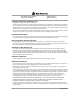
Installing a CPU Memory Upgrade in ASN and SN Platforms Phillips screwdriver Captive thumbscrews Component tray ASN0031A Figure 1-1. 1-4 Removing the ASN Component Tray 112944-B Rev.
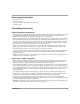
Installing a CPU Memory Upgrade in the ASN Removing DRAM SIMMs You may need to remove DRAM SIMMs if you are upgrading the ASN memory configuration (Figure 1-2). You must first remove the SIMM closest to the front of the tray. (Remember, the back of the tray is where the net module ports are exposed.) DRAM SIMMs ASN0032A Figure 1-2. 112944-B Rev.
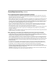
Installing a CPU Memory Upgrade in ASN and SN Platforms To remove a DRAM SIMM: 1. Press down the locking tab on each side of the SIMM to release it from the connector. The SIMM tilts back at a slight angle toward the front of the tray (Figure 1-3). Locking tabs Locking tabs Locking tabs ASN0033A Figure 1-3. 2. 1-6 Releasing the DRAM SIMM Grasp the top corners of the SIMM and pull it up and out of the connector. 112944-B Rev.
Installing a CPU Memory Upgrade in the ASN Installing DRAM SIMMs When you install DRAM SIMMs, make sure that the SIMMs are the same size. For example, you can install two 2-MB by 36 SIMMs for a 16-MB configuration; however, do not install one 1-MB by 36 and one 2-MB by 36 SIMM. Also, make sure that you are using the correct capacity Tag SIMM for your DRAM configuration (refer to Table 1-2). You must first install the SIMM closest to the back of the component tray. To install a DRAM SIMM: 1.
Installing a CPU Memory Upgrade in ASN and SN Platforms ASN0035A Figure 1-5. Installing the DRAM SIMM Removing the Tag SIMM You need to replace the Tag SIMM (Figure 1-6) if you are upgrading the ASN DRAM configuration to 32 MB. Table 1-2, shown earlier, lists the Tag SIMM requirements for the different DRAM configurations. Note: You do not need to replace the Tag SIMM if you are upgrading the DRAM configuration to 8 MB or 16 MB. To remove the Tag SIMM: 1.
Installing a CPU Memory Upgrade in the ASN Tag SIMM ASN0036A Figure 1-6. 2. 112944-B Rev. A Locating the Tag SIMM Press down the locking tab on each side of the SIMM to release it from the connector (Figure 1-7).
Installing a CPU Memory Upgrade in ASN and SN Platforms Locking tab Locking tab ASN0037A Figure 1-7. 1-10 Releasing the Tag SIMM 3. Grasp the top corners of the SIMM and gently pull it toward you at a slight angle. The SIMM naturally positions itself at an angle as you pull it. 4. Lift the SIMM out of the connector. 112944-B Rev.
Installing a CPU Memory Upgrade in the ASN Installing the Tag SIMM Before you perform this procedure, be sure to attach the antistatic wrist strap, as described earlier in this chapter. To install the Tag SIMM: 1. Grasp the SIMM by the top corners and place it into the connector at a slight angle (Figure 1-8). The SIMM is keyed to fit in the connector only one way. Notch ASN0038A Figure 1-8. 2. 112944-B Rev.
Installing a CPU Memory Upgrade in ASN and SN Platforms Labeling the ASN After you perform the DRAM SIMM upgrade, label the ASN rear panel and the ASN CPU with the Memory Size labels provided in the kit. Affixing the new labels is important because future repairs and upgrades will require that you correctly identify the memory configuration of your ASN. To label your ASN: Identify the existing Order Number label by looking at the rear panel of the ASN (Figure 1-9). 1.
Installing a CPU Memory Upgrade in the ASN 4. Apply the other Memory Size label to the CPU as follows: • On an ASN CPU (110341-xx or 107072-xx), apply the label to the right of the CPU Part Number label (Figure 1-10). • On an ASN2 CPU (112842-xx), apply the label below the CPU Part Number label, near the edge of the CPU (Figure 1-10). Memory Size label location CPU Part Number label CPU Serial Number label ASN0077A Memory Size label location on ASN2 CPU Figure 1-10.
Chapter 2 Installing a CPU Memory Upgrade in the SN This chapter describes how to install a CPU memory upgrade in a Bay Networks Switch Node (SN). After you review the SN SIMM types and attach the antistatic wrist strap, you will need a flat-tip screwdriver to complete the following steps: 1. Removing the SN CPU module 2. Removing DRAM SIMMs 3. Installing DRAM SIMMs 4. Removing the Tag SIMM 5. Installing the Tag SIMM 6. Labeling the SN 7.
Installing a CPU Memory Upgrade in ASN and SN Platforms The SN supports configurations of 16 and 32 MB of DRAM. Table 2-1 shows the DRAM SIMM requirements for each configuration. Table 2-1. DRAM Configurations in the SN Configuration SIMM Capacity Number of SIMMs 16 MB 2 MB by 36 2 32 MB 4 MB by 36 2 The capacity of the SIMM you use for Tag memory depends on the DRAM configuration. Table 2-2 shows the Tag SIMM requirements for each configuration. Table 2-2.
Installing a CPU Memory Upgrade in the SN 4. Plug the jack at the other end of the cable into the opening on the alligator clip. 5. Attach the alligator clip to any unpainted metal surface on the chassis. Removing the Switch Node CPU Module To remove the SN CPU module: 1. Turn off the Switch Node. 2. Disconnect any modem and console cables that are attached to the CPU module. 3. Remove the flash memory card from the PCMCIA slot by pressing the eject button to the right of the slot (Figure 2-1). 4.
Installing a CPU Memory Upgrade in ASN and SN Platforms Captive screw Flash memory card Module lever 10BASE-T tics / Diagnos Reset CPU 060 Console / Modem Console ATM OC-3 4 2 1 3 PCMCIA -TX 100 BASE Module lever 2 1 FX0021A Figure 2-1. 2-4 Removing the Switch Node CPU Module 112944-B Rev.
Installing a CPU Memory Upgrade in the SN Removing DRAM SIMMs You may need to remove DRAM SIMMs if you are upgrading the SN memory configuration (Figure 2-2). dem / Mo sole Con DRAM SIMMs CIA PCM FX0027A Figure 2-2. Locating the DRAM SIMMs To remove a DRAM SIMM: 1. Press down the locking tab on each side of the SIMM. The SIMM tilts back at a slight angle (Figure 2-3). 112944-B Rev.
Installing a CPU Memory Upgrade in ASN and SN Platforms FX0028A Figure 2-3. 2. 2-6 Releasing the DRAM SIMM Grasp the top corners of the SIMM and pull it up and out of the connector. 112944-B Rev.
Installing a CPU Memory Upgrade in the SN Installing DRAM SIMMs When you install DRAM SIMMs, make sure that the SIMMs are the same size. For example, you can install two 2-MB by 36 SIMMs for a 16-MB configuration; however, do not install one 1-MB by 36 and one 2-MB by 36 SIMM. Also, make sure that you are using the correct capacity Tag SIMM for your DRAM configuration (refer to Table 2-2). You must first install the SIMM closest to the back of the CPU. To install a DRAM SIMM: 1.
Installing a CPU Memory Upgrade in ASN and SN Platforms Removing the Tag SIMM You need to replace the Tag SIMM (Figure 2-6) if you are upgrading the SN DRAM configuration to 32 MB. Table 2-2, shown earlier, lists the Tag SIMM requirements for the different DRAM configurations. To remove the Tag SIMM: 1. Attach the antistatic wrist strap and remove the CPU, as described earlier in this chapter. Tag SIMM dem / Mo sole Con CIA PCM FX0031A Figure 2-6. Locating the Tag SIMM 2.
Installing a CPU Memory Upgrade in the SN Locking tab Locking tab FX0032A Figure 2-7. 3. Releasing the Tag SIMM Lift the SIMM out of the connector. Installing the Tag SIMM Before you perform this procedure, be sure to attach the antistatic wrist strap, as described earlier in this chapter. To install the Tag SIMM: 1. Grasp the SIMM by the top corners and place it into the connector at a slight angle (Figure 2-8). The SIMM is keyed to fit in the connector only one way. 112944-B Rev.
Installing a CPU Memory Upgrade in ASN and SN Platforms FX0033A Figure 2-8. 2. Installing the Tag SIMM Push down on the SIMM until the locking tabs snap into place. Labeling the Switch Node After you perform the DRAM SIMM upgrade, label the SN CPU with a new Memory Size label. Affixing the new label is important because future repairs and upgrades will require that you correctly identify the current memory configuration of your SN. To label your SN: 1.
Installing a CPU Memory Upgrade in the SN Serial Number label C36 Memory Size label CPU Part Number label CPU revision number FX0065A Figure 2-9. 112944-B Rev.
Installing a CPU Memory Upgrade in ASN and SN Platforms Replacing the Switch Node CPU Module To replace the SN CPU module: 1. Make sure the module levers are parallel to the front of the module. 2. Hold the CPU and align the sides of the module to the guides in the CPU slot (Figure 2-10). Captive screw Guide Module lever 10BASE-T tics / Diagnos Reset CPU 060 Console / Modem Console ATM OC-3 4 2 1 3 PCMCIA -TX 100 BASE 2 Module lever 1 FX0020A Figure 2-10.
Installing a CPU Memory Upgrade in the SN 3. Insert the module into the chassis until you feel resistance, then press firmly to make the connection with the Switch Node midplane. The module levers will automatically swing slightly forward when the module is in position. 4. Firmly push the levers inward (so that they are pointed toward you) to fully engage the locking mechanism (refer to Figure 2-10). 5.