
User's Manual


Installing a CPU Memory Upgrade in the SN
112944-B Rev. A 2-13
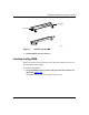
3.
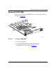
Insert the module into the chassis until you feel resistance, then press firmly to
make the connection with the Switch Node midplane.
The module levers will automatically swing slightly forward when the module is in
position.
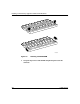
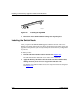
4. Firmly push the levers inward (so that they are pointed toward you) to fully
engage the locking mechanism (r
efer to Figure 2-10).
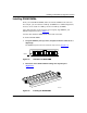
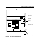
5. Using a flat-tip screwdriver, tighten the two captive retaining screws on the front
of the CPU module.
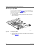
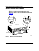
6. Turn on the Switch Node.
7. Observe the CPU module LEDs to determine whether the module is functioning
properly.
Refer to Installing and Maintaining the Switch Node Platform for information about
the LEDs.