
User's Manual


12
Part No. 115066-A Rev. B
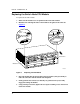
Replacing the Switch Node CPU Module
To replace the SN CPU module:
1.
Make sure the module levers are parallel to the front of the module.
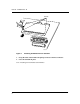
2.
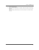
Hold the CPU and align the sides of the module to the guides in the CPU slot
(F
igure 9).
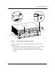
Figure 9. Replacing the CPU Module
3.
Insert the module into the chassis until you feel resistance, then press firmly to
make the connection with the Switch Node midplane.
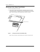
4.
Firmly push the levers inward (so that they are pointed toward you) to fully
engage the locking mechanism.
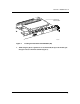
5.
Using a flat-tip screwdriver, tighten the two captive retaining screws on the front
of the CPU module.
100 BASE-TX
ATM OC-3
10BASE-T
FX0020A
1
2
1
2
4
3
PCMCIA
Reset
Console/ Diagnostics Console/ Modem
CPU 060
Captive
screw
Guide
Module lever
Module lever