Part No.
Copyright © 2000 Nortel Networks. All rights reserved. Printed in the USA. January 2000. The information in this document is subject to change without notice. The statements, configurations, technical data, and recommendations in this document are believed to be accurate and reliable, but are presented without express or implied warranty. Users must take full responsibility for their applications of any products specified in this document.
EC Declaration of Conformity This product conforms (or these products conform) to the provisions of Council Directive 89/336/EEC and 73/23/EEC. The Declaration of Conformity is available on the Nortel Networks World Wide Web site at http://libra2.corpwest.baynetworks.com/cgi-bin/ndCGI.exe/DocView/.
customer should be aware that compliance with the above conditions may not prevent the degradation of service in some situations. Canada Requirements Only (continued) Repairs to certified equipment should be coordinated by a representative designated by the supplier. Any repairs or alterations made by the user to this equipment, or equipment malfunctions, may give the telecommunications company cause to request the user to disconnect the equipment.
FCC Part 68 Compliance Statement This equipment complies with Part 68 of FCC Rules. All direct connections to telephone network lines must be made using standard plugs and jacks compliant with FCC Part 68. Please note the following: 1. You are required to request service from the telephone company before you connect the unit to a network.
5. You are required to notify the telephone company when you disconnect the unit from the network. Nortel Networks NA Inc. Software License Agreement NOTICE: Please carefully read this license agreement before copying or using the accompanying software or installing the hardware unit with pre-enabled software (each of which is referred to as “Software” in this Agreement). BY COPYING OR USING THE SOFTWARE, YOU ACCEPT ALL OF THE TERMS AND CONDITIONS OF THIS LICENSE AGREEMENT.
WARRANTY OF MERCHANTABILITY OR FITNESS FOR A PARTICULAR PURPOSE. Licensee is responsible for the security of its own data and information and for maintaining adequate procedures apart from the Software to reconstruct lost or altered files, data, or programs. 4. Limitation of liability.
NETWORKS UNLESS NORTEL NETWORKS GIVES ITS EXPRESS WRITTEN CONSENT, INCLUDING AN EXPRESS WAIVER OF THE TERMS OF THIS AGREEMENT.
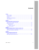
Contents Preface Before You Begin ............................................................................................................. xv Text Conventions ............................................................................................................. xv Acronyms ......................................................................................................................... xv Hard-Copy Technical Manuals ........................................................................
Chapter 4 Connecting Cables Connecting Communications Cables ..............................................................................4-1 Connecting to an Ethernet Interface ........................................................................4-2 Connecting to the ATM T1/E1 Interface ...................................................................4-3 Connecting to the ATM T1 Interface ..................................................................4-3 Connecting to the ATM E1 Interface ........
Figures Figure 1-1. Passport 5430 System Processor Card with PMC Module ......................1-2 Figure 1-2. System Processor Card with PMC Module ..............................................1-3 Figure 1-3. Passport 5430 System Processor Card Diagnostic LEDs .......................1-4 Figure 2-1. Removing a PMC Module Filler Panel .....................................................2-2 Figure 2-2. Installing a PMC Module .........................................................................
Tables Table 1-1. System Processor Card Console LEDs ..................................................1-5 Table 1-2. System Processor Card Port LEDs ..........................................................1-6 Table 1-3. Installation Tasks and Procedures ...........................................................1-7 Table 4-1. Console Parameters ................................................................................4-6 Table 4-2. Console Parameters ......................................
Preface In this guide, the Passport™ 5430 Multiservice Access Switch is referred to as the Passport 5430. Before You Begin This guide is intended for qualified service personnel who need to install or replace a system processor card. A qualified service person should have appropriate technical training and experience and be aware of the hazards involved in installing and replacing CRUs. Text Conventions This guide uses the following text conventions: italic text Indicates new terms and book titles.
Installing a System Processor Card n the Passport 5430 Multiservice Access Switch Hard-Copy Technical Manuals You can print selected technical manuals and release notes free, directly from the Internet. Go to support.baynetworks.com/library/tpubs/. Find the product for which you need documentation. Then locate the specific category and model or version for your hardware or software product.
Chapter 1 Passport 5430 System Processor Overview This document supplements Installing and Operating the Passport 5430 Multiservice Access Switch. Follow the hardware installation steps in that manual, then refer to this document for information specific to the system processor card. Warning: The system processor card is designed to operate in the Passport 5430 Multiservice Access Switch only.
Installing a System Processor Card in the Passport 5430 Multiservice Access Switch System Processor Hardware Description The Passport 5430 system processor hardware has two types of components: • A system processor card • ATM T1/E1 PMC module The system processor card (Figure 1-1) can accommodate one ATM T1/E1 PMC module. The PMC module plugs into connectors on the system processor card. The system processor card, with PMC module installed, installs into the Passport 5430 chassis.
Passport 5430 System Processor Overview System Processor Card The system processor card includes two flash card slots, a PMC module opening, two 10/100BASE-TX connectors, and a console connector (Figure 1-2). Two DIMM connectors on the system processor card provide 64 Mb of memory. 10/100BASE-TX connectors PMC module m ste r Sy esso oc Pr Console connector Flash card slots FBR0052A Figure 1-2.
Installing a System Processor Card in the Passport 5430 Multiservice Access Switch Port 2 Module 1 Port 1 System processor TX/RX SPD Link Console Module 2 ISDN BRI withNT1 D B1 DD B2 SYNC LOOP YEL ALM RED ALM Run Mod2 Boot Fan cPCI Sys Module 1 Port 1 System Processor SPD Link Console PCMCIA 1 COM Module 4 PCMCIA 2 PS1 WAN Run PS2 Mod2 Boot Fan cPCI PCI Slot 1 Sys 5V FLASH ONLY RLSD Module 2 Module 1 Voice Processor Insert Daul T1/E1 Serial COM Extract PCI Slot
Passport 5430 System Processor Overview Table 1-1 describes the system processor card console LEDs. Table 1-1. System Processor Card Console LEDs LED State Meaning PS1 Off Power is off. On (green) Power supply is operating. Rapid flashing (green) Power supply failed. Off Power is off. On (green) Redundant power supply (optional) is operating. Rapid flashing (green) Redundant power supply failed. Off Fan is operating properly. On (green) One or more cooling fans stopped operating.
Installing a System Processor Card in the Passport 5430 Multiservice Access Switch Table 1-1. System Processor Card Console LEDs (continued) LED State Meaning Sys Off System processor card was not tested. On (green) System processor card is operating properly. Slow flashing (green) System processor card is running its diagnostic tests. Rapid flashing (green) System processor card failed its diagnostic tests. Off Expansion cards or voice processor cards not tested.
Passport 5430 System Processor Overview How to Use This Guide Refer to Table 1-3, identify the scenario that matches your objective, and follow the associated steps. Table 1-3. Installation Tasks and Procedures If you need to... You must... Install a system processor card 1. Install the PMC module onto the system processor card. See “Installing a PMC Module Onto a System Processor Card” on page 2-2. 2.
Chapter 2 Installing a PMC Module Onto the System Processor Card Complete the steps in this chapter to install an ATM T1/E1 PMC module onto the system processor card. Each system processor card can accommodate one ATM T1/E1 PMC module. Caution: Electrostatic discharge can damage hardware. You must wear the antistatic wrist strap on your arm whenever you handle printed circuit boards. Refer to the instructions enclosed with your antistatic wrist strap to attach it.
Installing a System Processor Card in a Passport 5430 Multiservice Access Switch Installing a PMC Module Onto a System Processor Card To install a PMC module onto a system processor card: 1. If necessary (first time installation), push the PMC module filler panel out from behind the card bezel (Figure 2-1). m ste r Sy esso oc Pr FBR0113A Figure 2-1.
Installing a PMC Module Onto the System Processor Card 2. Orient the PMC module so that its connectors are aligned with the connectors on the system processor card (Figure 2-2). m ste r Sy esso oc Pr FBR0054A Figure 2-2. Installing a PMC Module 3. Press the PMC module into the connectors on the system processor card (Figure 2-2). Make sure the PMC module is properly seated in the connectors.
Installing a System Processor Card in a Passport 5430 Multiservice Access Switch 4. Secure the PMC module with the four screws provided (Figure 2-3). m ste r Sy esso oc Pr FBR0055A Figure 2-3. Securing the PMC to the Expansion Card 5. Install the system processor card into the Passport 5430 chassis. For instructions, see “Installing a System Processor Card” on page 3-1.
Installing a PMC Module Onto the System Processor Card Removing and Replacing a PMC Module Occasionally it may be necessary to remove or replace a PMC module on the system processor card. To remove and replace a PMC module on a system processor card: 1. Remove the system processor card from the Passport 5430 chassis. For instructions, see “Removing the System Processor Card” on page 3-5. 2. Locate the installed PMC module you wish to remove or replace. 3.
Installing a System Processor Card in a Passport 5430 Multiservice Access Switch 4. Remove the PMC module by pulling it straight up and out of the system processor card sockets (Figure 2-5). m ste r Sy esso oc Pr FBR0114A Figure 2-5. Removing a PMC Module 5. 2-6 If required, follow the instructions in “Installing a PMC Module Onto a System Processor Card” on page 2-2 to install a replacement PMC module.
Chapter 3 Installing the System Processor Card This chapter describes how to install and replace a Passport 5430 system processor card. Installing a System Processor Card To install a system processor card: 1. Turn off the Passport 5430. 2. If present, turn off the redundant power supply. 3. Put on an antistatic wrist strap. Caution: Electrostatic discharge can damage hardware. You must wear the antistatic wrist strap on your arm whenever you handle printed circuit boards.
Installing a System Processor Card in the Passport 5430 Multiservice Access Switch 6. Hold the system processor card with the components facing up (Figure 3-1). 10/100BASE-TX connectors PMC module m ste r Sy esso oc Pr Console connector Flash card slots FBR0052A Figure 3-1.
Installing the System Processor Card 7. Slide the system processor card into the slot, making sure that the slot guides engage both sides of the card assembly (Figure 3-2).
Installing a System Processor Card in the Passport 5430 Multiservice Access Switch 10. Using a Phillips screwdriver, tighten 2 captive screws in the extractors and the 2 captive screws above the extractors (Figure 3-3). Module 3 System Processor U ISDN BRI withNT1 PCI Slot 1 COM Module 4 Voice Processor COM PCI Slot 2 Module 5 Expansion Card Expansion Card Telco Remote Console PCI Slot 3 PCI Slot 4 4 V.34 Modem FBR0092A Figure 3-3. Tightening the Extractor Screws 11.
Installing the System Processor Card Removing the System Processor Card Occasionally it may be necessary to remove a system processor card. To remove a system processor card: 1. Turn the power switch on each of the power supplies to off (0) position (Figure 3-4). Power switch DC OK DC OK PS1 PS2 Power supplies FBR0031A Figure 3-4. Passport 5430 Power Switch 2. If present, turn off the redundant power supply. 3. Attach an antistatic wrist strap.
Installing a System Processor Card in the Passport 5430 Multiservice Access Switch 5. Module 3 Using a Phillips screwdriver, loosen the four captive screws that fasten the system processor card to the chassis(Figure 3-5). System Processor U ISDN BRI withNT1 PCI Slot 1 COM Module 4 Voice Processor COM PCI Slot 2 Module 5 Expansion Card Expansion Card Telco Remote Console PCI Slot 3 PCI Slot 4 4 V.34 Modem FBR0106A Figure 3-5.
Installing the System Processor Card 6. Gently pull the inside of the board extractors at each end of the system processor card away from you (Figure 3-6). The extractors swing open, pulling the card out of the backplane connectors.
Installing a System Processor Card in the Passport 5430 Multiservice Access Switch 10. Reinstall the PMC module on the replacement system processor card if necessary. a. Hold the PMC module with the connectors facing down. b. Place the PMC module on the system processor card and press down on the PMC module to seat it in the socket (Figure 3-7). m ste r Sy esso oc Pr FBR0054A Figure 3-7.
Installing the System Processor Card c. Insert and tighten the 4 screws using a Phillips screwdriver to secure the PMC to the system processor card (Figure 3-8). m ste r Sy esso oc Pr FBR0055A Figure 3-8.
Installing a System Processor Card in the Passport 5430 Multiservice Access Switch 11. Hold the replacement system processor card with the components facing up (Figure 3-9). 10/100BASE-TX connectors PMC module m ste r Sy esso oc Pr Console connector Flash card slots FBR0052A Figure 3-9.
Installing the System Processor Card 12. Slide the system processor card into PCI Slot 1, making sure that the slot guides engage both sides of the card assembly (Figure 3-10).
Installing a System Processor Card in the Passport 5430 Multiservice Access Switch 15. Using a Phillips screwdriver, tighten the 2 captive screws in the extractors and the 2 captive screws above the extractors (Figure 3-11). Module 3 System Processor U ISDN BRI withNT1 PCI Slot 1 COM Module 4 Voice Processor COM PCI Slot 2 Module 5 Expansion Card Expansion Card Telco Remote Console PCI Slot 3 PCI Slot 4 4 V.34 Modem FBR0092A Figure 3-11. Tightening the Extractor Screws 16.
Chapter 4 Connecting Cables This chapter describes how to connect cables to the system processor card and AC power source, as follows: Topic Page Connecting Communications Cables 4-1 Connecting a Management Console 4-6 Connecting to the AC Power Source 4-14 Connecting Communications Cables Gather the communications equipment and cabling that you will attach to the Passport 5430. If you do not have the appropriate cables, see the Cable Guide.
Installing a System Processor Card in the Passport 5430 Multiservice Access Switch Then, complete the steps in the applicable sections: Topic Page Connecting to an Ethernet Interface 4-2 Connecting to the ATM T1/E1 Interface 4-3 Connecting a PC Console 4-6 Connecting a Terminal Console 4-8 Connecting an External Modem 4-10 Connecting to an Ethernet Interface To connect an unshielded twisted pair (UTP) cable to the system processor module: 1.
Connecting Cables Connecting to the ATM T1/E1 Interface The ATM T1/E1 PMC module provides one T1 or E1 interface. To connect to the ATM T1 interface, see the next section, “Connecting to the ATM T1 Interface.” To connect to the ATM E1 interface, see “Connecting to the ATM E1 Interface” on page 4-4. Connecting to the ATM T1 Interface To connect to the ATM T1 interface on an installed ATM T1/E1 PMC module: 1. Route the cable in the cable kit (Order No.
Installing a System Processor Card in the Passport 5430 Multiservice Access Switch Connecting to the ATM E1 Interface To connect to the ATM E1 interface on an installed ATM T1/E1 PMC module: 1. Route the cable through the cable loom slot corresponding to PCI slot 1. For instructions, see Installing and Operating the Passport 5430 Multiservice Access Switch. 2. Insert the RJ-48C cable connector into the ATM T1/E1 interface (Figure 4-2). 3.
Connecting Cables 5. Turn the coaxial cable to the right until the key on the connector clicks into the notch on the coaxial cable (Figure 4-4). 1 2 3 FBR0076A Figure 4-4. 6. Connecting a Coaxial Cable to the Coaxial-to-Twisted Pair Cable Adapter Arrange the cable in the cable loom. For instructions, see Installing and Operating the Passport 5430 Multiservice Access Switch.
Installing a System Processor Card in the Passport 5430 Multiservice Access Switch Connecting a Management Console You can use the front-panel console port to connect a PC or terminal. You can also connect a telephone line directly to the optional V.34 console modem adapter module for an out-of-band management console. Using a local console, you can monitor the results of the Passport 5430 startup diagnostics and set the boot configuration.
Connecting Cables You can do this either through the termiinal emulation program or the PC control panel and the instructions in your PC documentation. 3. Route the cable through the cable loom slot corresponding to PCI slot 1. For instructions, see Installing and Operating the Passport 5430 Multiservice Access Switch. 4. Insert the blue RJ-45 receptacle end of the console cable into the Passport 5430 Console port (Figure 4-5).
Installing a System Processor Card in the Passport 5430 Multiservice Access Switch 6. Connect the DB-9 end of the cable to the communications data port on the back of the laptop PC. Connecting a Terminal Console To connect a terminal console to the Passport 5430, make sure that you have the RJ-45 to DB-9 cable (Order No. AA0011026) that Nortel Networks shipped with the Passport 5430 and a DB-9 to DB-25 adapter (not supplied), then complete the following steps: 1.
Connecting Cables 5. Module 3 Attach the DB-25 end of the adapter to the console host connector (Figure 4-6). System Processor U ISDN BRI withNT1 COM PCI Slot 1 Module 4 Voice Processor COM PCI Slot 2 Module 5 Expansion Card PCI Slot 3 Expansion Card Telco Remote Console V.34 Modem COMM 20 mA PR KB FBR0109A Figure 4-6.
Installing a System Processor Card in the Passport 5430 Multiservice Access Switch Connecting an External Modem A modem provides remote access to the Passport 5430. It is a good idea to connect a modem in case the Passport 5430 experiences system problems. Note: Before you turn on the Passport 5430 for the first time to boot and configure the router, you must connect a PC or terminal console. To use a modem connection as a management console, you can connect a telephone line directly to the optional V.
Connecting Cables To connect an external modem to the Passport 5430, you need an AT or Hayes compatible modem and the RJ-45 to DB-9 cable and adapter kit (Order No. AA0011026) that Nortel Networks provided with the Passport 5430. To connect an external console modem: 1. Configure the modem, using the parameters in Table 4-3. See the modem user guide for instructions. 2. Turn off the modem. 3. Route the cable through the cable loom slot corresponding to PCI slot 1.
Installing a System Processor Card in the Passport 5430 Multiservice Access Switch Module 3 System Processor U ISDN BRI withNT1 COM PCI Slot 1 Module 4 Voice Processor COM PCI Slot 2 Module 5 Expansion Card PCI Slot 3 Expansion Card Telco Remote Console PCI Slot 4 V.34 Modem PHONE DIAL NMS DTE FBR0100A Figure 4-7.
Connecting Cables 5. Attach one end of the modem adapter to the connector on the console cable, then tighten the screws (Figure 4-8). Console cable connector Rotate to tighten screw Modem adapter Rotate to tighten screw FBR0108A Figure 4-8. Attaching the Modem Adapter 6. Connect the complete cable unit to the modem RS-232 data communications interface. 7. Arrange the cable in the cable loom. For instructions, see Installing and Operating the Passport 5430 Multiservice Access Switch.
Installing a System Processor Card in the Passport 5430 Multiservice Access Switch Connecting to the AC Power Source Danger: Make sure that the power switch on each Passport 5430 power supply is in the off (0) position before you connect the power cables. To connect a power cable to the Passport 5430: 1. Connect the power cable to the power connector on the power supply (Figure 4-9). Power switch (off) DC OK DC OK PS1 PS2 To power outlet Figure 4-9.