Installing a V.34 Console Modem Module in a BayStack ARN Router Part No. 114313 Rev.
4401 Great America Parkway Santa Clara, CA 95054 8 Federal Street Billerica, MA 01821 Copyright © 1988–1996 Bay Networks, Inc. All rights reserved. Printed in the USA. November 1996. The information in this document is subject to change without notice. The statements, configurations, technical data, and recommendations in this document are believed to be accurate and reliable, but are presented without express or implied warranty.
Electromagnetic Emissions Meets requirements of: FCC Part 15, Class A EN 55 022 (CISPR 22:1985), Class A VCCI Class 1 ITE Canada Requirements Only Canada CS-03 Rules and Regulations Note: The Canadian Department of Communications label identifies certified equipment. The certification means that the equipment meets certain telecommunications network protective operations and safety requirements. The Department does not guarantee the equipment will operate to the user's satisfaction.
Canada Requirements Only (continued) D. O. C. Explanatory Notes: Equipment Attachment Limitations The Canadian Department of Communications label identifies certified equipment. This certification meets certain telecommunication network protective, operational and safety requirements. The department does not guarantee the equipment will operate to the users satisfaction.
Canada Requirements Only (continued) Canadian Department of Communications Radio Interference Regulations This digital apparatus (Access Feeder Node, Access Link Node, Access Node, Access Stack Node, Backbone Concentrator Node, Backbone Concentrator Node Switch, Backbone Link Node, Backbone Link Node Switch, Concentrator Node, Feeder Node, Link Node) does not exceed the Class A limits for radio-noise emissions from digital apparatus as set out in the Radio Interference Regulations of the Canadian Department
Bay Networks Software License Note: This is Bay Networks basic license document. In the absence of a software license agreement specifying varying terms, this license -- or the license included with the particular product -- shall govern licensee’s use of Bay Networks software. This Software License shall govern the licensing of all software provided to licensee by Bay Networks (“Software”).
Bay Networks Software License (continued) 9. Licensee shall not reverse assemble, reverse compile, or in any way reverse engineer the Software. [Note: For licensees in the European Community, the Software Directive dated 14 May 1991 (as may be amended from time to time) shall apply for interoperability purposes. Licensee must notify Bay Networks in writing of any such intended examination of the Software and Bay Networks may provide review and assistance.] 10.
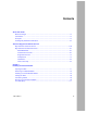
Contents About This Guide Before You Begin ............................................................................................................. xv Conventions ..................................................................................................................... xv Acronyms ......................................................................................................................... xv Ordering Bay Networks Publications .....................................................
Figures Figure 1-1. Figure 1-2. Figure 1-3. Figure 1-4. Figure 1-5. Figure 1-6. ARN Power Switch (Off) and Cable .........................................................1-2 Loosening the Captive Screws ................................................................1-2 Removing the ARN Enclosure .................................................................1-3 Removing the Screws ..............................................................................1-4 Removing the Filler Plate for the V.
Tables Table 1-1. 114313 Rev. A Boot Status LEDs ...................................................................................
About This Guide If you are responsible for installing Bay Networks™ hardware, read this guide to learn how to install a V.34 Console Modem module replacement or upgrade in a BayStack™ Advanced Remote Node™ (ARN™) router. Before You Begin Make sure that you are running the latest version of Bay Networks Site Manager and router software. The ARN requires Router Software Version 11.00 Rev. 4n or later.
Installing a V.34 Console Modem Module in a BayStack ARN Router Ordering Bay Networks Publications To purchase additional copies of this document or other Bay Networks publications, order by part number from the Bay Networks Press™ at the following telephone or fax numbers: • Telephone - U.S./Canada • Telephone - International • Fax 1-888-4BAYPRESS 1-510-490-4752 1-510-498-2609 You can also use these numbers to request a free catalog of Bay Networks Press product publications. xvi 114313 Rev.
Technical Support and Online Services To ensure comprehensive network support to our customers and partners worldwide, Bay Networks Customer Service has Technical Response Centers in key locations around the globe: • • • • • Billerica, Massachusetts Santa Clara, California Sydney, Australia Tokyo, Japan Valbonne, France The Technical Response Centers are connected via a redundant Frame Relay Network to a Common Problem Resolution system, enabling them to transmit and share information, and to provide liv
Installing a V.34 Console Modem Module in a BayStack ARN Router Bay Networks Customer Service If you purchased your Bay Networks product from a distributor or authorized reseller, contact that distributor’s or reseller’s technical support staff for assistance with installation, configuration, troubleshooting, or integration issues. Customers can also purchase direct support from Bay Networks through a variety of service programs.
Technical Support and Online Services Bay Networks Information Services Bay Networks Information Services provide up-to-date support information as a first-line resource for network administration, expansion, and maintenance. This information is available from a variety of sources. World Wide Web The Bay Networks Customer Support Web Server offers a diverse library of technical documents, software agents, and other important technical information to Bay Networks customers and partners.
Installing a V.34 Console Modem Module in a BayStack ARN Router Support Source CD This CD-ROM -- sent quarterly to all contracted customers -- is a complete Bay Networks Service troubleshooting knowledge database with an intelligent text search engine.
Technical Support and Online Services InfoFACTS InfoFACTS is the Bay Networks free 24-hour fax-on-demand service. This automated system has libraries of technical and product documents designed to help you manage and troubleshoot your Bay Networks products. The system responds to a fax from the caller or to a third party within minutes of being accessed. To use InfoFACTS in the United States or Canada, call toll-free 1-800-786-3228. Outside North America, toll calls can be made to 1-408-764-1002.
Chapter 1 Installing the Console Modem Complete the steps in this chapter to install a V.34 Console Modem module in an ARN router. To install the module, you 1. Open the ARN enclosure to access the component tray. 2. Attach an antistatic wrist strap. Caution: Electrostatic discharge can damage hardware. You must wear the antistatic strap whenever you remove, install, or handle printed circuit boards. 3. If present, remove an existing V.34 Console Modem module from the ARN. 4. Install the new V.
Installing a V.34 Console Modem Module in a BayStack ARN Router Redundant power supply cable Power cable UL Redundant Power UL 100-240~ 1.2A 50-60Hz ARN0017A Figure 1-1. ARN Power Switch (Off) and Cable 4. Remove any console cabling from the back panel. 5. Loosen the two captive screws that secure the top enclosure to the ARN component tray (Figure 1-2). Be sure to loosen the screws all the way. Enclosure UL 100-240~ 1.
Installing the Console Modem 6. Remove all network cables from the front panel. 7. Place the ARN tray on a table or other work surface. 8. Holding the ARN front panel so that it does not move, slide the ARN enclosure away from the front panel and component tray (Figure 1-3). RLSD3 RLSD4 Tx RLSD5 Rx D ISDN BRI withNT1 1 DD B1 Cl k B2 Run Boot Tx Fail Pwr RPS Fan Base Adapter1 Adapter2 Expansion BayStac Advanced Remote Node DCM PCMCIA Rx 2 Figure 1-3. 9.
Installing a V.34 Console Modem Module in a BayStack ARN Router Removing an Installed Module To remove an existing V.34 Console Modem module from the ARN base module: 1. Locate the installed module and remove the four screws that secure it to the base module (Figure 1-4). ARN0046A Figure 1-4. 1-4 Removing the Screws 2. Grasping the edges of the module, pull straight up and lift the module out of the base module connector socket. 3.
Installing the Console Modem Installing a Console Modem Module To install a V.34 Console Modem module: 1. Remove and set aside the two screws that secure the back panel EMI filler plate (Figure 1-5). ARN0079A Figure 1-5. Removing the Filler Plate for the V.34 Console Modem Slot 2. Remove the filler plate. 3. Attach two mounting screw standoffs at either side of the base module’s V.34 modem connector (Figure 1-6). The standoff mounts came with the console modem kit. 114313 Rev.
Installing a V.34 Console Modem Module in a BayStack ARN Router Screw mount V.34 modem module connector ARN0044B Figure 1-6. Installing Standoff Screw Mounts for the V.34 Console Modem Module 4. 1-6 Hold the module by its edges, with the base module connector facing down (Figure 1-7). 114313 Rev.
Installing the Console Modem ARN0045A Figure 1-7. Positioning the Module 5. Place the console modem module into the base module connector socket and press down to seat the module firmly in the socket. 6. Secure the module using four screws (Figure 1-8). ARN0046B Figure 1-8. 114313 Rev.
Installing a V.34 Console Modem Module in a BayStack ARN Router Closing the ARN To replace the ARN enclosure: 1. Remove the antistatic wrist strap. 2. Align the enclosure top around the base module component tray and slide the enclosure in until it meets the front panel (Figure 1-9). If you meet resistance, lift up slightly on the enclosure, and center the component tray between the enclosure edges. t Power UL 100-240~ 1.
Installing the Console Modem 3. Secure the two captive screws that hold the cover to the component tray. 4. Reconnect any cabling you removed. 5. Plug in the power cord and, if applicable, the redundant power supply cable. Refer to Figure 1-1. 6. Attach the label that came in the upgrade kit to the ARN back panel. Connecting Cables Before reconnecting the ARN to the network, connect an RJ-11 modem cable to the new V.34 interface (Figure 1-10).
Installing a V.34 Console Modem Module in a BayStack ARN Router U 1 D B1 DD B2 Tx 10BaseT AUI COM3 RLSD3 Rx RLSD4 Cl RLSD5 ISDN BRI COM4 COM5 Serial Ethernet 2 2 Tx RLSD COM Serial 10BaseT AUI Run Pwr Boot RPS Adapter1 DCM Fail Fan Adapter2 Base Expansion PCMCIA Rx Cl BayStack Ethernet 1 AUI Run Pwr Base Boot RPS Adapter1 DCM Fail Fan Adapter2 PCMCIA Advanced Remote Node Expansion ARN0059A Figure 1-11.
Installing the Console Modem 6. After completing the diagnostic testing procedure, the boot process begins. The Run and Boot LEDs indicate the boot status as shown in Table 1-1. Table 1-1. Boot Status LEDs Boot Status Run LED Boot LED Local Boot Off On Netboot (attempting) Off Flashing Netboot (downloading) Flashing On Interrupted (using ARN monitor) Flashing Flashing 7.