
User's Manual


Installing a V.34 Console Modem Module in a BayStack ARN Router
1-2
114313 Rev. A
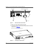
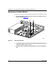
Figure 1-1. ARN Power Switch (Off) and Cable
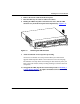
4.
Remove any console cabling from the back panel.
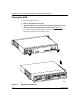
5.
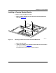
Loosen the two captive screws that secure the top enclosure to the ARN
component tray (F
igure 1-2).
Be sure to loosen the screws all the way.
Figure 1-2. Loosening the Captive Screws
ARN0017A
Redundant power supply cable
Power cable
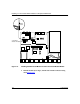
Redundant Power
U
L
U
L
100-240~
1.2A
50-60Hz
ARN0049A
U
L
U
L
100-240~
1.2A
50-60Hz
Console Modem
Redundant Power
Enclosure
Back panel