Part No.
Copyright © 2000 Nortel Networks. All rights reserved. Printed in the USA. January 2000. The information in this document is subject to change without notice. The statements, configurations, technical data, and recommendations in this document are believed to be accurate and reliable, but are presented without express or implied warranty. Users must take full responsibility for their applications of any products specified in this document.
EC Declaration of Conformity This product conforms (or these products conform) to the provisions of Council Directive 89/336/EEC and 73/23/EEC. The Declaration of Conformity is available on the Nortel Networks World Wide Web site at http://libra2.corpwest.baynetworks.com/cgi-bin/ndCGI.exe/DocView/.
Canada Requirements Only (continued) Repairs to certified equipment should be coordinated by a representative designated by the supplier. Any repairs or alterations made by the user to this equipment, or equipment malfunctions, may give the telecommunications company cause to request the user to disconnect the equipment.
FCC Part 68 Compliance Statement This equipment complies with Part 68 of FCC Rules. All direct connections to telephone network lines must be made using standard plugs and jacks compliant with FCC Part 68. Please note the following: 1. You are required to request service from the telephone company before you connect the unit to a network.
5. You are required to notify the telephone company when you disconnect the unit from the network. Nortel Networks NA Inc. Software License Agreement NOTICE: Please carefully read this license agreement before copying or using the accompanying software or installing the hardware unit with pre-enabled software (each of which is referred to as “Software” in this Agreement). BY COPYING OR USING THE SOFTWARE, YOU ACCEPT ALL OF THE TERMS AND CONDITIONS OF THIS LICENSE AGREEMENT.
ANY WARRANTY OF MERCHANTABILITY OR FITNESS FOR A PARTICULAR PURPOSE. Licensee is responsible for the security of its own data and information and for maintaining adequate procedures apart from the Software to reconstruct lost or altered files, data, or programs. 4. Limitation of liability.
NETWORKS UNLESS NORTEL NETWORKS GIVES ITS EXPRESS WRITTEN CONSENT, INCLUDING AN EXPRESS WAIVER OF THE TERMS OF THIS AGREEMENT.
Contents Preface Before You Begin ............................................................................................................. xv Text Conventions ............................................................................................................. xv Acronyms ......................................................................................................................... xv Hard-Copy Technical Manuals ........................................................................
Figures Figure 1-1. Passport 5430 Expansion Card with PMC Module ..................................1-2 Figure 1-2. Dual Synchronous PMC Module ..............................................................1-3 Figure 2-1. Removing a PMC Module Filler Panel .....................................................2-2 Figure 2-2. Installing a PMC Module ..........................................................................2-3 Figure 2-3. Securing the PMC to the Expansion Card ........................
Tables Table 1-1. 306623-A Rev 00 Installation Tasks and Procedures ...........................................................
Preface In this guide the Passport 5430 Multiservice Access Switch is referred to as the Passport 5430. Before You Begin This guide is intended for qualified service personnel who need to install or replace an expansion card in a Passport 5430 Multiservice Access Switch. A qualified service person should have appropriate technical training and experience and be aware of the hazards involved in installing and replacing CRUs.
Installing an Expansion Card in a Passport 5430 Multiservice Access Switch Hard-Copy Technical Manuals You can print selected technical manuals and release notes free, directly from the Internet. Go to support.baynetworks.com/library/tpubs/. Find the product for which you need documentation. Then locate the specific category and model or version for your hardware or software product.
Chapter 1 Passport 5430 Expansion Card Overview This document supplements Installing and Operating the Passport 5430 Multiservice Access Switch. Follow the hardware installing steps in that manual, then refer to this document for information specfic to the expansion card. Warning: The expansion card is designed to operate in the Passport 5430 Multiservice Access Switch only. Attempting to use the expansion card in any other product may be hazardous and invalidates the regulatory approval.
Installing an Expansion Card in a Passport 5430 Multiservice Access Switch Expansion Hardware Description The Passport 5430 expansion hardware has two types of components: • An expansion card • PMC modules The expansion card (Figure 1-1) can accommodate two dual synchronous PMC modules. The PMC modules plug into connectors on the expansion card. The expansion card, with PMC module(s) installed, installs into the Passport 5430 chassis. rd ion Ca ns a xp E FBR0010A Figure 1-1.
Passport 5430 Expansion Card Overview A dual synchronous PMC module is shown in Figure 1-2. FBR0015A Figure 1-2.
Installing an Expansion Card in a Passport 5430 Multiservice Access Switch How to Use This Guide Refer to Table 1-1, identify the scenario that matches your objective, and follow the associated steps. Table 1-1. Installation Tasks and Procedures If you need to... You must... Install an expansion card 1. Install PMC modules onto the expansion card. See “Installing a PMC Module Onto an Expansion Card” on page 2-1. 2. Remove the blank filler panel. See “Removing the Filler Panel” on page 3-4. 3.
Chapter 2 Installing PMC Modules Onto the Expansion Card Complete the steps in this chapter to install PMC modules onto the expansion card. Each expansion card can accommodate two PMC modules. Caution: Electrostatic discharge can damage hardware. You must wear the antistatic wrist strap on your arm whenever you handle printed circuit boards. Refer to the instructions enclosed with your antistatic wrist strap to attach it.
Installing an Expansion Card in a Passport 5430 Multiservice Access Switch rd ion Ca ns pa Ex FBR0058A Figure 2-1.
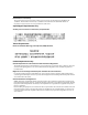
Installing PMC Modules Onto the Expansion Card 2. Orient the PMC module so that its connectors are aligned with the connectors on the expansion card (Figure 2-2). ard nC sio an p Ex PMC module openings FBR0006A Figure 2-2. Installing a PMC Module 3. Press the PMC module into the connectors on the expansion card (Figure 2-2). Make sure the PMC module is properly seated in the connectors.
Installing an Expansion Card in a Passport 5430 Multiservice Access Switch Flip the expasnion card over (component side down) and secure the PMC module with the four screws provided (Figure 2-3). Ex pa 4. ns ion Ca rd FBR0007A Figure 2-3. Securing the PMC to the Expansion Card 5. Repeat steps 1 through 4 to install another PMC module onto the expansion card. 6. Install the expansion card into the Passport 5430 chassis. For instructions, see “Installing an Expansion Card” on page 3-1.
Installing PMC Modules Onto the Expansion Card Removing and Replacing a PMC Module Occasionally it may be necessary to remove or replace a PMC module on the expansion card. To remove and replace a PMC module on an expansion card: 1. Follow the instructions in “Removing an Expansion Card” on page 3-5 to remove the expansion card from the Passport 5430 chassis. 2. Locate the installed PMC module you wish to remove or replace. 3.
Installing an Expansion Card in a Passport 5430 Multiservice Access Switch 4. Flip the expansion card over again (component side up) and remove the PMC module by pulling it straight up and out of the expansion card sockets (Figure 2-5). rd ion Ca ns pa Ex FBR0112A Figure 2-5. Removing a PMC Module 5. 2-6 If required, follow the instructions in “Installing a PMC Module Onto an Expansion Card” on page 2-1 to install a replacement PMC module.
Chapter 3 Installing Expansion Cards This chapter describes how to install and remove expansion cards. Installing an Expansion Card To install an expansion card: 1. Turn off the Passport 5430. 2. If a redundant power supply is installed, turn it off. 3. Put on an antistatic wrist strap. Caution: Electrostatic discharge can damage hardware. You must wear the antistatic wrist strap on your arm whenever you handle printed circuit boards. 4. Install one or two PMC modules onto the expansion card.
Installing an Expansion Card in a Passport 5430 Multiservice Access Switch 5. If necessary (first time installation) remove the blank filler panel covering the slot on the Passport 5430 chassis. For instructions, see “Removing the Filler Panel” on page 3-4. 6. Hold the expansion card with the components facing up. 7.
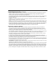
Installing Expansion Cards 10. Tighten the two captive screws to secure the card in the chassis (Figure 3-2) Module 3 System Processor U ISDN BRI withNT1 COM PCI Slot 1 Module 4 Voice Processor PCI Slot 2 COM Module 5 Expansion Card PCI Slot 3 Expansion Card Telco Remote Console PCI Slot 4 V.34 Modem FBR0094A Figure 3-2. Tightening the Extractor Screws 11. Connect the cabling to the new interface. For cabling information, see the applicable module-specific Supplement. 12. Turn power on.
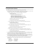
Installing an Expansion Card in a Passport 5430 Multiservice Access Switch Removing the Filler Panel To remove the filler panel: 1. Using a Phillips screwdriver, remove the two screws that fasten the filler panel to the slot (Figure 3-3).
Installing Expansion Cards Removing an Expansion Card Occaisionally it may be necessary to remove an expansion card. To remove an expansion card: 1. Turn off the Passport 5430. 2. If present, turn off the redundant power supply. 3. Attach an antistatic wrist strap. Caution: Electrostatic discharge can damage hardware. You must wear the antistatic wrist strap on your arm whenever you handle printed circuit boards. Module 3 4. Disconnect any cables attached to the ports on the expansion card. 5.
Installing an Expansion Card in a Passport 5430 Multiservice Access Switch 6. Gently push the inside of the board extractors at each end of the expansion card away from you (Figure 3-5).