Part No. P1013653 03 September 2, 2004 Business Communications Manager Analog Devices Configuration Guide for systems with version 3.
Copyright © 2004 Nortel Networks All rights reserved March 2004. The information in this document is subject to change without notice. The statements, configurations, technical data, and recommendations in this document are believed to be accurate and reliable, but are presented without express or implied warranty. Users must take full responsibility for their applications of any products specified in this document. The information in this document is proprietary to Nortel Networks NA Inc.
Contents 3 Contents Preface . . . . . . . . . . . . . . . . . . . . . . . . . . . . . . . . . . . . . . . . . . . . . . . . . . . . . . . 5 Before you begin . . . . . . . . . . . . . . . . . . . . . . . . . . . . . . . . . . . . . . . . . . . . . . . . . . . . . . 5 Acronyms used in this guide . . . . . . . . . . . . . . . . . . . . . . . . . . . . . . . . . . . . . . . . . . . . . 5 How to get help . . . . . . . . . . . . . . . . . . . . . . . . . . . . . . . . . . . . . . . . . . . . . . . . . . . . . .
Contents P1013653 03
Preface This guide explains how to program analog devices on a Business Communications Manager system. New hardware and features described in this guide requires that your Business Communications Manager system is running release 3.6 or higher. This chapter includes the following general information: • Before you begin • Acronyms used in this guide • How to get help Before you begin This guide is intended for the system administrator who manages the overall telephony operations of the system.
Preface How to get help USA and Canada Authorized Distributors - ITAS Technical Support Telephone: 1-800-4NORTEL (1-800-466-7835) If you already have a PIN Code, you can enter Express Routing Code (ERC) 196#. If you do not yet have a PIN Code, or for general questions and first line support, you can enter ERC 338#. Website: http://www.nortelnetworks.
Chapter 1 Introduction Analog device DNs are programmed in the same way as digital telephone DNs. However, programming settings will vary, depending on the type of analog device and how it is connected to the Business Communications Manager system. There are two types of analog devices: voice and data communications. Refer to the following table for examples of voice and data communication devices.
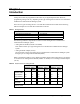
Chapter 1 Introduction The following table shows a detailed view of DN Record headings in Unified Manager. Table Legend † o Required programming settings for basic operations of an analog device. Optional programming settings for digital telephones and analog devices. Programming settings not relevant to analog devices.
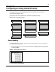
Chapter 2 Configuring an analog device DN record This chapter reviews the basic programming settings for analog devices on the Business Communications Manager system. The following table shows a detailed view of the basic programming settings.
Chapter 2 Configuring an analog device DN record 3 Click on the DN record (DN XXXX) for an analog device. 4 Click on the General heading. Figure 2 General screen example 5 Use the table below to assign a name to the analog device. Table 5 General record fields Attribute Values Description Name
Chapter 2 Configuring an analog device DN record 11 • You can assign any number of line pools to an analog device. If all lines in the pool are taken, the user receives a busy signal. To assign lines 1 Click on the key beside the Line access heading in the DN record. 2 Click on the Line assignment heading. 3 Click the Add button. 4 Type a line number in the Line box. 5 Click the Save button. 6 On the navigation tree, click the Line nnn you just created.
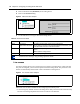
Chapter 2 Configuring an analog device DN record 3 Enter a line pool identifier. <- Pool A to O>. 4 Click the Save button. The line pool identifier appears under the Line pool access heading. To assign a prime line 1 Click on the Line access heading in the DN record. Figure 4 Line access screen example 2 Use the table below to select a prime line. The prime line is the line that is automatically selected when a call is made from an analog device.
Chapter 2 Configuring an analog device DN record 2 13 Seven capabilities fields must be reviewed for analog device compatibility and are shown with a red asterisk in Figure 6. Figure 6 Capabilities fields screen example * * * * * * * 3 Use the information in the following table to configure seven specific capabilities fields (if required) for an analog device. Table 8 Capabilities fields Attribute Values Description Handsfree Auto Standard None Set this value to None for analog devices.
Chapter 2 Configuring an analog device DN record Table 8 Capabilities fields (Continued) Attribute Values Description Page zone Page Zone (1 to 6) None This setting is for analog telephones. Assigns an analog telephone to a page zone. A zone is any group of telephones that you want to group together for paging regardless of their location. You can assign one of six zones to each telephone. Paging Y or N This setting is for analog telephones.
Chapter 2 Configuring an analog device DN record 3 15 Use the information in the following table to configure an external hotline setting. Table 9 Hotline values Attribute Values Description External External # Facility Value: Use line nnn Use prime line Pool code Use routing table Use this setting for modems credit card verifiers and fax machines. Enter pause (F78) for the external number. The pause feature inserts a 1.5-second delay before the data device starts dialing.
Chapter 2 Configuring an analog device DN record Table 10 ATA settings (Continued) Attribute Values Description ATA use On site Off site Select the location of the analog device. The Off site value is supported on analog devices connected to an ASM 8+ module. ATA tones Y or N Defines whether the analog device receives system tones. Set this value to N for modems and fax machines. Set this value to Y for analog telephones.