Installing the ARE 32-MB Memory Upgrade Kit Part No. 112831 Rev.
4401 Great America Parkway Santa Clara, CA 95054 8 Federal Street Billerica, MA 01821 Copyright © 1988–1996 Bay Networks, Inc. All rights reserved. Printed in the USA. April 1996. The information in this document is subject to change without notice. The statements, configurations, technical data, and recommendations in this document are believed to be accurate and reliable, but are presented without express or implied warranty.
Electromagnetic Emissions Meets requirements of: FCC Part 15, Class A EN 55 022 (CISPR 22:1985), Class A and Class B VCCI Class 1 ITE Canada Requirements Only Canada CS-03 Rules and Regulations Note: The Canadian Department of Communications label identifies certified equipment. The certification means that the equipment meets certain telecommunications network protective operations and safety requirements. The Department does not guarantee the equipment will operate to the user's satisfaction.
Canada Requirements Only (continued) D. O. C. Explanatory Notes: Equipment Attachment Limitations The Canadian Department of Communications label identifies certified equipment. This certification meets certain telecommunication network protective, operational and safety requirements. The department does not guarantee the equipment will operate to the users satisfaction.
Canada Requirements Only (continued) Canadian Department of Communications Radio Interference Regulations This digital apparatus (Access Feeder Node, Access Link Node, Access Node, Access Stack Node, Backbone Concentrator Node, Backbone Concentrator Node Switch, Backbone Link Node, Backbone Link Node Switch, Concentrator Node, Feeder Node, Link Node) does not exceed the Class A limits for radio-noise emissions from digital apparatus as set out in the Radio Interference Regulations of the Canadian Department
Bay Networks Software License Note: This is Bay Networks basic license document. In the absence of a software license agreement specifying varying terms, this license — or the license included with the particular product — shall govern licensee’s use of Bay Networks software. This Software License shall govern the licensing of all software provided to licensee by Bay Networks (“Software”). Bay Networks will provide licensee with Software in machine-readable form and related documentation (“Documentation”).
Bay Networks Software License (continued) 9. Licensee shall not reverse assemble, reverse compile, or in any way reverse engineer the Software. [Note: For licensees in the European Community, the Software Directive dated 14 May 1991 (as may be amended from time to time) shall apply for interoperability purposes. Licensee must notify Bay Networks in writing of any such intended examination of the Software and Bay Networks may provide review and assistance.] 10.
Contents Installing the ARE 32-MB Memory Upgrade Modules Required Tools ................................................................................................................... 1 Shipment Contents ............................................................................................................ 2 How to Get Help ................................................................................................................ 2 Removing the VBM Module .....................................
Figures Figure 1. Figure 2. Figure 3. Figure 4. Figure 5. Removing the Mounting Screws ................................................................. 4 Aligning the VBM Module ............................................................................ 5 Locating the SIMM Sockets ........................................................................ 6 Inserting a SIMM into a Socket ................................................................... 7 Locking a SIMM in Place ..........................
Tables Table 1. Shipment Contents .....................................................................................
Installing the ARE 32-MB Memory Upgrade Modules This document describes how to install the 32-MB memory upgrade modules on an ATM Routing Engine (ARE) processor module. The memory upgrade is supported by Router Software Version 9.01 and later.
Installing the ARE 32-MB Memory Upgrade Kit Shipment Contents Table 1 lists the contents of the 32-MB memory upgrade kit (Order No. AG1311008). If any parts are damaged or missing, contact the Bay Networks Technical Response Center in your area. Table 1.
Installing the ARE 32-MB Memory Upgrade Modules Removing the VBM Module If you are upgrading your ARE processor module from 16 MB to 32 MB, you must first remove the existing VBM module, before you can install the new one. If you are upgrading from 8 MB to 32 MB, there is no VMB module to remove. In this case, proceed to the next section, “Installing the VBM Module.” To remove the existing VBM module, you must first remove the ARE processor module from the router.
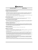
Installing the ARE 32-MB Memory Upgrade Kit Phillips screws Phillips screws A320001A.eps Figure 1. 2. Removing the Mounting Screws Grasp the VBM module by the edges and lift it to remove it from the ARE processor module. Store the VBM module in an antistatic bag. 3. Follow the steps in the next section to install the new VBM module. Installing the VBM Module If you have not already done so, remove the ARE processor module from the router.
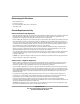
Installing the ARE 32-MB Memory Upgrade Modules To install the VBM module: 1. Align the two connectors on the VBM module with the connectors on the ARE processor module (Figure 2). Also, align the mounting holes on the VBM module with the standoffs on the ARE processor module. Then press the upgrade module into place. Mounting holes Mounting holes 4 standoffs Connectors A320003A Figure 2. Aligning the VBM Module 2. In each of the four mounting holes on the VBM module, insert a Phillips screw.
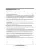
Installing the ARE 32-MB Memory Upgrade Kit Removing SIMMs from the ARE Processor Module 1. Using Figure 3 as a reference, locate SIMM sockets U7 and U14 on your ARE processor module. There will be a SIMM in each of these sockets. U7 U14 Figure 3. 2. 6 Locating the SIMM Sockets To remove the SIMMs currently populating sockets U7 and U14: a. Pull back on the retainers grasping the edges of the SIMM to release it. b. Gently lift up and pull out the SIMM.
Installing the ARE 32-MB Memory Upgrade Modules Installing the Memory Upgrade SIMMs This procedure assumes you have already removed the SIMMs from the appropriate sockets as described in the previous section. Your upgrade kit contains two identical SIMMs. To install them: 1. Grasp one of the SIMM by the edges, and turn it so the notch at the center of the SIMM faces the center of socket U7 (Figure 4). Notch Figure 4. Inserting a SIMM into a Socket 2.
Installing the ARE 32-MB Memory Upgrade Kit When the SIMM is properly inserted, the two tiny vertical black poles on the SIMM socket should line up with the two holes in the SIMM. Retainer Black poles on socket must line up with holes in SIMM A320009A Figure 5. Locking a SIMM in Place 4. Repeat Steps 1 through 3 to install the other SIMM in socket U14. 5. Install the ARE processor module in the BN®.