Part No.
Copyright © 2000 Nortel Networks All rights reserved. October 2000. The information in this document is subject to change without notice. The statements, configurations, technical data, and recommendations in this document are believed to be accurate and reliable, but are presented without express or implied warranty. Users must take full responsibility for their applications of any products specified in this document. The information in this document is proprietary to Nortel Networks NA Inc.
EC Declaration of Conformity This product conforms (or these products conform) to the provisions of Council Directive 89/336/EEC and 73/23/EEC.
Canada Requirements Only (continued) Repairs to certified equipment should be coordinated by a representative designated by the supplier. Any repairs or alterations made by the user to this equipment, or equipment malfunctions, may give the telecommunications company cause to request the user to disconnect the equipment.
FCC Part 68 Compliance Statement This equipment complies with Part 68 of FCC Rules. All direct connections to telephone network lines must be made using standard plugs and jacks compliant with FCC Part 68. Please note the following: 1. You are required to request service from the telephone company before you connect the unit to a network.
Nortel Networks NA Inc. Software License Agreement NOTICE: Please carefully read this license agreement before copying or using the accompanying software or installing the hardware unit with pre-enabled software (each of which is referred to as “Software” in this Agreement). BY COPYING OR USING THE SOFTWARE, YOU ACCEPT ALL OF THE TERMS AND CONDITIONS OF THIS LICENSE AGREEMENT. THE TERMS EXPRESSED IN THIS AGREEMENT ARE THE ONLY TERMS UNDER WHICH NORTEL NETWORKS WILL PERMIT YOU TO USE THE SOFTWARE.
for the security of its own data and information and for maintaining adequate procedures apart from the Software to reconstruct lost or altered files, data, or programs. 4. Limitation of liability.
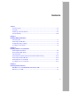
Contents Preface Text Conventions .............................................................................................................xvi Acronyms .........................................................................................................................xvi Hard-Copy Technical Manuals ........................................................................................xvii How to Get Help .............................................................................................
Figures Figure 1-1. Link Module Slots in a BLN Platform .......................................................1-2 Figure 1-2. Link Module Slots in a BLN-2 Platform ....................................................1-2 Figure 1-3. Link Module Slots in a BCN Platform .......................................................1-3 Figure 1-4. Jumpers on the ARE DS-3 Link Module ..................................................1-5 Figure 1-5. Link Module Captive Screws (BCN Example) ...................
Tables Table 1-1. ARE DS-3 and ARE E-3 Jumper Settings ...............................................1-6 Table 3-1. Functions of the DS-3, E-3, and SONET/SDH Link Module LEDs Table 3-2. ARE Processor LEDs .............................................................................3-4 Table 3-3. ARE Processor Diagnostic Codes ...........................................................3-5 ........
Preface Read this guide if you are responsible for installing any of the following Nortel Networks™ Asynchronous Transfer Mode (ATM) link or processor modules in a Backbone Node (BN®) platform: • • • • • ATM Routing Engine (ARE) OC-3 Single Mode or Multimode link module ARE STS-3/STM-1 SONET/SDH Multimode Fiber (MMF) or Single Mode Fiber (SMF) link module ARE DS-3 link module ARE E-3 link module ARE processor module This guide describes how to • Install an ARE link module in these BN platforms: -- Backb
Installing ATM Link Modules and Routing Engines in BN Platforms Text Conventions This guide uses the following text conventions: bold text Indicates command names and options and text that you need to enter. Example: Enter show ip {alerts | routes}. Example: Use the dinfo command. italic text Indicates file and directory names, new terms, book titles, and variables in command syntax descriptions. Where a variable is two or more words, the words are connected by an underscore.
Preface SELV safety extra-low voltage SMF Single Mode Fiber SONET Synchronous Optical Network SRM-F System Resource Module-Front SRM-L System Resources Module-Link STM Synchronous Transfer Mode STS Synchronous Transport Signal TNV telecommunications network voltage VBM Virtual Buffer Memory Hard-Copy Technical Manuals You can print selected technical manuals and release notes free, directly from the Internet. Go to the support.baynetworks.com/library/tpubs/ URL.
Installing ATM Link Modules and Routing Engines in BN Platforms How to Get Help If you purchased a service contract for your Nortel Networks product from a distributor or authorized reseller, contact the technical support staff for that distributor or reseller for assistance.
Chapter 1 Installing ATM Link Modules Note: In this guide, the term ATM link module includes all Nortel Networks ARE link modules (ARE OC-3, DS-3, E-3, and SONET/SDH) , unless referring to a specific model. The term does not include the ARE processor module. To install an ATM link module, complete these preliminary tasks as needed: • Choose a slot • Remove a link module • Configure jumper settings This chapter describes each of these tasks, as well as how to install the ATM link module.
Installing ATM Link Modules and Routing Engines in BN Platforms Captive screws 100 - 240V~ 10.
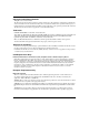
Installing ATM Link Modules Link module slots Power OK 14 13 12 11 10 9 8 S R M L 6 5 4 3 2 1 Power OK Power OK Power OK QMC0012A Figure 1-3. Link Module Slots in a BCN Platform Removing a Link Module If there are no empty slots in your BN platform, you must remove a link module to install the ATM link module. When replacing a configured link module, you must delete all configured circuits (ports) on the slot so the BN platform software can properly configure the new link module.
Installing ATM Link Modules and Routing Engines in BN Platforms Removing a link module with the power on distrupts the services that slot provides. However, after the slot fails to receive packets, the other link modules in the chassis resynchronize their routing tables and continue uninterrupted. The procedure for removing a link module is the same for the BLN, BLN-2, and BCN platforms: 1. Disconnect any exterior cables from the link module. 2. Attach an antistatic wrist strap.
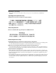
Installing ATM Link Modules S1 S2 ALM0005A Figure 1-4. Jumpers on the ARE DS-3 Link Module Before installing the ARE DS-3 or E-3 link module, refer to Table 1-1 to ensure that the jumper settings match your configuration.
Installing ATM Link Modules and Routing Engines in BN Platforms Table 1-1. ARE DS-3 and ARE E-3 Jumper Settings Option Setting Chassis ground connection for BNC transmit interface Connected Jumper S1 Disconnected S1 Chassis ground connection for BNC receive interface Connected S2 Disconnected S2 Inserting the Link Module Insert the link module in the BLN, BLN-2, or BCN platform as follows: 1. Attach an antistatic wrist strap. BN platforms and link modules ship with an antistatic wrist strap.
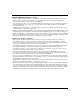
Installing ATM Link Modules Power OK 14 13 12 11 10 9 8 SRML 7 6 5 4 3 2 1 Power OK Power OK ® A RE E-3 S E AR 3 E- IL FA IL FA MODULE RESET ATMC RESET SW LOAD Power OK TEST RDI LINK TX RX RX ALM0002A Figure 1-5. 4. 114951-B Rev 00 Link Module Captive Screws (BCN Example) Once you are done accessing the interior of the chassis, remove the antistatic wrist strap.
Chapter 2 Installing ARE Processor Modules To install an ARE processor module, you must first 1. Remove the front bezel of your BN platform. 2. Remove the electromagnetic compatibility (EMC) shield from the front panel to access the interior. 3. Choose a slot. 4. Remove the board retainer bracket (BLN and BLN-2 only). 5. Remove the air flow module (unless the slot you want to use already contains a processor module). 6.
Installing ATM Link Modules and Routing Engines in BN Platforms Removing the Front Bezel You must remove the BN platform front bezel (front cover) to access the interior. Note: Keep the front bezel on during normal operation to comply with air flow requirements. To remove the front bezel from the BLN (Figure 2-1) and BLN-2 (Figure 2-2): 1. Using both hands, pull the bottom of the front bezel forward. 2. Remove the bezel from the chassis.
Installing ARE Processor Modules POWER B A C K B O N E N O D E RUN BOOT DIAG RESET Pull bottom ALM0011A Figure 2-2. Removing the BLN-2 Front Bezel To remove the front bezel from the BCN (Figure 2-3): 114951-B Rev 00 1. Using both hands, pull the top of the front bezel forward. 2. Remove the bezel from the chassis.
Installing ATM Link Modules and Routing Engines in BN Platforms Pull top POWER B A C K B O N E Figure 2-3.
Installing ARE Processor Modules Removing the EMC Shield You must remove the EMC shield to access the processor modules in BN platforms. Caution: Do not operate a BN platform with the EMC shield removed for more than 5 minutes. Without the EMC shield, the BN platform may overheat. In addition, the BCN contains temperature sensors that may not detect an overheating condition without the shield in place. To remove the EMC shield (Figure 2-4): 1. Attach an antistatic wrist strap.
Installing ATM Link Modules and Routing Engines in BN Platforms ! POWER B A C K B O N E RUN BOOT DIAG N O D E RESET WARNING HIGH ENERGY PRESENT Power unit OFF and disconnect power cord BEFORE accessing this product. Refer to your installation/service manual for instructions ATTENTION EQUIPEMENT SOUS HAUTE TENSION Debrancher le cordon d’alimentation avant d’enlever le couvercle.
Installing ARE Processor Modules Choosing a Slot You can install the ARE processor module in • • • Slots 2 through 5 in the BLN platform (Figure 2-5) Slots 2 through 5 in the BLN-2 platform (Figure 2-6) Slots 1 through 6 and Slots 8 through 14 in the BCN platform (Figure 2-7) Insert ARE processor modules only in slots opposite ARE link modules. ! POWER B A C K B O N E N O D E RUN BOOT DIAG WARNING RESET HIGH ENERGY PRESENT Power unit OFF and disconnect power cord BEFORE accessing this product.
Installing ATM Link Modules and Routing Engines in BN Platforms FRE/FRE-2/ARE processor modules (Slots 2-5) POWER B A C K B O N E N O D E Extractor RUN BOOT DIAG RESET Board retainer bracket SRM-F (Slot 1) ALM0008A Figure 2-6.
Installing ARE Processor Modules FRE/FRE-2/ARE processor modules (slots 1-6) SRM-F (slot 7) FRE/FRE-2/ARE processor modules (slots 8-14) POWER B A C K B O N E N O D E RUN BOOT DIAG RESET Extractor 1 2 3 4 5 6 7 8 9 10 11 12 13 14 ALM0009A Figure 2-7.
Installing ATM Link Modules and Routing Engines in BN Platforms Removing the Board Retainer Bracket (BLN and BLN-2 Only) If you have a BLN or BLN-2 platform, remove the board retainer bracket shown earlier in Figure 2-5 (BLN) and Figure 2-6 (BLN-2): 1. Use a screwdriver to remove the screw connecting the board retainer bracket to the chassis. 2. Gently pull the bottom of the board retainer bracket to remove it.
Installing ARE Processor Modules BACK BON E NO DE POW RU ER N BO DIAOT G RES ET BN0022B Figure 2-9. Removing an Air Flow Module Removing a Processor Module Danger: A potential energy hazard exists during hot-swap service of processor modules. Do not remove more than two adjacent modules without powering off the BN platform. To remove a processor module: 1. Gently pull the inside of the board extractors at the end of the module toward you (Figure 2-10).
Installing ATM Link Modules and Routing Engines in BN Platforms Extractors FRE0005A Figure 2-10. Using the Extractors to Remove a Processor Module Inserting the Processor Module Insert the ARE processor module as follows: 1. Holding the board extractors open (refer to Figure 2-10), slide the module into the card guides of the desired slot.
Installing ARE Processor Modules 4. 5. 6. If you just installed the ARE processor module in a BLN or BLN-2 platform, replace the board retainer bracket: a. Slide the top of the board retainer bracket into its designated ridge and align the bottom of the bracket with the screw hole at the bottom of the chassis (refer to Figure 2-5 or 2-6). b. Using a screwdriver, secure the bracket to the chassis. Replace the EMC shield as follows (refer to Figure 2-4): a.
Chapter 3 Checking Status Indicators Check the LEDs on the ATM link modules or the ARE processor module to verify that a module is operating after installation. Note: We recommend that you issue the diags command to the associated slot, using the Nortel Networks Technician Interface, immediately after you insert a link module. (Refer to Using Technician Interface Software if you use router software or Troubleshooting and Testing if you use BayStream software.
Installing ATM Link Modules and Routing Engines in BN Platforms E DH AR T/S NE SO IL FA MODULE RESET ATMC RESET SW LOAD TEST RDI RECEIVE LINK TRANSMIT ALM0006A Figure 3-2. ARE SONET/SDH Link Module LEDs Table 3-1 describes the LED functions, which are identical for the DS-3, E-3, and SONET/SDH interface link modules. Table 3-1. Functions of the DS-3, E-3, and SONET/SDH Link Module LEDs LED Function MODULE RESET Lights when the link module is resetting.
Checking Status Indicators ARE Processor LEDs Figure 3-3 shows the ARE processor LEDs, as well as the following: • • • Harpoon Diagnostic Console Monitor (HDCM) port and button A reserved port Memory card ejector Detail: Group 3 1 2 3 4 5 6 7 8 9 10 11 1213 14 15 16 171819 20 2122 232425 26 27 28 29 30 3132 Memory Reserved HDCM HDCM Card Port Button Ejector Port 12345678 Group 1 Figure 3-3. 1234 Group 2 Group 3 ALM0004A ARE Processor LEDs Table 3-2 describes the ARE processor LEDs.
Installing ATM Link Modules and Routing Engines in BN Platforms Table 3-2. ARE Processor LEDs LED Description Group 1 1 (Green) The ARE module is transmitting on PPX A. 2 (Green) The ARE module is transmitting on PPX B. 3 (Green) The ARE module is transmitting on PPX C. 4 (Green) The ARE module is transmitting on PPX D. 5 (Green) The ARE module is flow-controlling on PPX A. 6 (Green) The ARE module is flow-controlling on PPX B. 7 (Green) The ARE module is flow-controlling on PPX C.
Checking Status Indicators Table 3-2. ARE Processor LEDs (continued) LED Description 16 (Amber) The Technician Interface is running on this slot. 17 through 25 (Green) Transmit and Receive ATMizers are active. These LEDs indicate bus activity. 26 (Amber) Motorola Power PC microprocessor memory coherency operations are taking place. Memory coherency operations occur when the two Power PCs share data between their data caches.