BCM450 Rls 6.
BCM450 System Start Up Copyright © 2010 Avaya Inc. All Rights Reserved. Notices While reasonable efforts have been made to ensure that the information in this document is complete and accurate at the time of printing, Avaya assumes no liability for any errors. Avaya reserves the right to make changes and corrections to the information in this document without the obligation to notify any person or organization of such changes.
BCM450 System Start Up Downloading documents For the most current versions of documentation, see the Avaya Support. Web site: http://www.avaya.com/support Contact Avaya Support Avaya provides a telephone number for you to use to report problems or to ask questions about your product. The support telephone number is 1-800-242-2121 in the United States. For additional support telephone numbers, see the Avaya Web site: http://www.avaya.
BCM450 System Start Up Table of Contents System Start Up ................................................................ 6 Overview .......................................................................................... 6 Required Information ....................................................................... 6 Standalone .........................................................................................................6 LAN Connection .........................................................
BCM450 System Start Up ASM Analog Station Module Configuration .....................................................66 Combination Modules ......................................................................................67 Connecting the BCM to the Network .............................................. 68 Registering IP Terminals................................................................ 68 Additional Information ....................................................
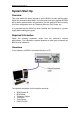
BCM450 System Start Up System Start Up Overview This guide details the steps required to set the BCM to a basic working state. When the procedures described in this document have been applied the BCM will be able to perform basic call operations, and the system will then be ready for further configuration such as Telephony Services, Call Centre, etc. It is assumed that the BCM has been installed and connected to a power supply before starting this guide.
BCM450 System Start Up License File (Keycode File) Telephony Template Start DN of the system Public/Private Received digits CallPilot Region CallPilot Password CallPilot User Interface (UI) Style CallPilot Attendant DN Lines to assign to CallPilot Auto-Attendant LAN Connection In this situation, the BCM is connected to a Local Area Network.
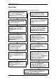
BCM450 System Start Up Flow Chart The flow chart outlines the steps involved in System Start-Up: Obtain the required information from the network administrator etc: refer to the Required Information section of this guide. Set the name of the BCM: refer to the Setting the System Name section of this guide. Obtain the Keycode file: refer to the Obtaining a Keycode file section of this guide. Ensure the date & Time is correct: refer to the Setting the Date & Time section of this guide.
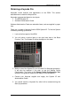
BCM450 System Start Up Obtaining a Keycode File Keycodes unlock features and applications on the BCM. This section describes how to obtain the Keycode file. Keycodes are generated based on two inputs: The BCM System ID Software Authorisation Codes Software Authorisation Codes are orderable items, and are supplied in paper form. There are a number of ways to find the BCM System ID. To find the System ID without powering up the BCM: 1. Look at the front panel of the BCM. 2.
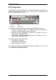
BCM450 System Start Up PC Configuration The BCM has a dedicated OAM port. It is recommended that you perform any maintenance/configuration from this port. There are also 2 dedicated LAN ports for connecting to the network A PC/laptop can be configured to connect to the BCM OAM in two ways: Set your PC/laptop to obtain an IP Address automatically (preferred , as DHCP is always operating on the OAM port) Manually set your PC/laptop’s IP Address (IP Address: 10.10.11.2, Subnet Mask: 255.255.255.
BCM450 System Start Up Physical Connection to the BCM The BCM OAM port can accommodate either a patch cable or a cross-over cable. One end of the cable is connected to the PC network card, the other end to the OAM port of the BCM. Testing the IP connection using Ping When a physical connection has been made, you should next test the connection by “pinging” the BCM. This test is performed on the Laptop/PC that is connected to the BCM. 1. Go to the Start button on your Windows desktop, and select Run.
BCM450 System Start Up 2. Type cmd and press OK. This will bring up the MS-DOS / command prompt. 3. Type ping followed by the default IP Address of the LAN port you are connected to (OAM = 10.10.11.1, LAN Port = 192.168.2.2). Press Enter. 4. There are differing responses that may now be displayed. a. If a Reply is received from the BCM (as displayed below) the IP connection is working. b.
BCM450 System Start Up Installing the Element Manager Application Element Manager is the application that allows configuration of the BCM via a PC/laptop. Note: You must ensure you are using the correct version of Element Manager. The version supplied with the BCM will be the correct version. The application should be installed on the PC/laptop that is required to perform configuration. Note: Java Runtime Environment must be installed on the PC used to access Application Launcher. Visit www.java.
BCM450 System Start Up 3. If you see the following information box, click Yes. 4. You may be presented with a second certificate error message. To avoid seeing the message again, tick the Always trust content from this publisher box, and click Yes. 5. Again, you may be presented with a security warning. Tick the Always trust content from this publisher box to avoid seeing the message in future, and click Run. 14 NN40010-317 Issue 1.2 BCM450 Rls 6.
BCM450 System Start Up 6. You will be asked to enter the BCM account credentials. Tick the Save Credentials and Auto-Login boxes for easier future access. Click OK when the account details have been entered. 7. In the Application Launcher window, ensure the Main tab is selected. Click on the BCM button to ensure the required list of applications are present. NN40010-317 Issue 1.2 BCM450 Rls 6.
BCM450 System Start Up 8. From the list of Applications, select Business Element Manager and click on the Run button. 9. The download progress will display. 10. In the Node List Import window, you can browse to a folder containing a previous BEM installation (e.g. to import previous BEM nodes) and click on Open. Alternatively, click on Cancel to continue. 16 NN40010-317 Issue 1.2 BCM450 Rls 6.
BCM450 System Start Up 11. If there hasn’t been a previous installation of Element Manager an “empty” version (i.e. no preconfigured settings or Elements) will be presented. If you selected a folder containing a previous installation in the last step, the existing nodes will be listed in the Element Navigation Panel. Note: Subsequent launches of Element Manager from Application Launcher or via Start, Programs or desktop shortcut will show configured Elements, and retain Element Manager settings.
BCM450 System Start Up 2. Alternatively, double-click on the Business Element Manager desktop icon. 3. You will be presented with the Element Manager interface. 4. Open the Network Elements folder and select the IP Address of the BCM. 18 NN40010-317 Issue 1.2 BCM450 Rls 6.
BCM450 System Start Up 5. Enter the User Name of the BCM in the User Name field, by default this is nnadmin. Then enter the Password in the Password field, by default the password is PlsChgMe!. Click the Connect button. 6. A warning screen will appear, read the warning and click OK. 7. You will be presented with the Element Manager interface. NN40010-317 Issue 1.2 BCM450 Rls 6.
BCM450 System Start Up Software Keycodes Note: If you have already applied the Keycodes via the Startup Profile, you can proceed to the Initialising CallPilot Manager section. Keycodes are entered in the Keycodes section of Element Manager, and are entered as a file containing a range of features Note: When entering the Keycode file, you may be asked to reboot the BCM. Certain features such as VoIP G/W Trunks, require the BCM to be rebooted. Use the following procedure to load a Keycode file. 1.
BCM450 System Start Up 4. Browse to the location of the file and select it. Click Open. 5. The features will be applied and viewable in the Feature Licenses table. NN40010-317 Issue 1.2 BCM450 Rls 6.
BCM450 System Start Up 6. If you prompted to reboot the BCM after entering the keycode file select the Administration tab followed by Utilities, Reboot and then click the Reboot button. Note: The feature status change in the keycodes panel may take up to one minute to display depending on the system load and component response. You can refresh the keycode window to see the feature status change, after adding the keycode file, by selecting the refresh button in Element Manager.
BCM450 System Start Up 2. In the Configuration tab open the System heading and click on IP Subsystem. 3. Click on the LAN Interfaces tab. Select the Customer LAN row, and click Modify in the lower part of the screen. NN40010-317 Issue 1.2 BCM450 Rls 6.
BCM450 System Start Up 4. Enter the IP Settings as required. You can choose to: Obtain an IP Address, Subnet Mask, and Default Gateway automatically (refer to the DHCP Guide for more information on BCM and DHCP). Enter an IP Address, Subnet Mask and Default Gateway manually. Note: If there is an existing DHCP server on the network, it is recommended that you specify a static IP Address for the BCM. See the network administrator about obtaining a static IP Address.
BCM450 System Start Up 7. If Obtaining an IP Address dynamically, tick the Obtain IP address dynamically box. You will see the following WARNING box. 8. Click OK in the WARNING box, and click OK again in the Modify IP Settings box. 9. You may lose your connection to Element Manager. You will not need to reboot the BCM. Click the OK button, and reconnect to the BCM using the new IP address (unless connected via the OAM port). 10.
BCM450 System Start Up 11. DNS settings can also be entered, if you are not receiving this information via DHCP. In the IP Subsystem area, click on the General Settings tab, and enter the relevant DNS information in the DNS Settings fields. Configuring DHCP The BCM can be used as the main DHCP server for the network, or it can be used to provide DHCP information to IP Sets only. Alternatively, DHCP can be disabled on the BCM if DHCP requirements are being provided by another device on the network.
BCM450 System Start Up 2. Select the General Settings tab. It is normally selected by default. 3. Configure the DHCP server attributes as required. 4. The BCM does not automatically create an address range of IP Addresses for allocation to DHCP clients. If the BCM is to be configured as a DHCP server (for IP Phones only or all devices) you will need to create an address range. Click on the Address Ranges tab. NN40010-317 Issue 1.2 BCM450 Rls 6.
BCM450 System Start Up 5. Click on the Add button. Enter the following settings and click OK: From IP Address: Start of the range of IP Addresses to be issued to DHCP clients To IP Address: End of the range of IP Addresses to be issued to DHCP clients. Default Gateway: Gateway address for this range to use. 6. This range will be issued to DHCP clients, if the BCM is configured to be a DHCP server.
BCM450 System Start Up Attribute Lease time(s) Value Description node is used only as a last resort. Default: H-node The amount of time before a DHCP lease expires and the device must request a new IP address. Default: 604800 seconds Setting the System Name This name is used for identification purposes. 1. From the Configuration tab, open the System folder to expand it. 2. Select Identification from the System folder. 3.
BCM450 System Start Up Setting the Date and Time 1. From the Configuration tab, open the System folder to expand it. 2. Select Date and Time from the System folder. The Date and Time panel displays. 3. Select the appropriate Date and Time Source. 30 NN40010-317 Issue 1.2 BCM450 Rls 6.
BCM450 System Start Up 4. If setting the Date and Time Source as NTP, click on the Modify button. 5. Configure the NTP settings as required, and click OK. 6. If setting the Date and Time Source as Manual, click on the Date and Time drop down arrow, and use the control to select the correct date and time. Click OK when finished. NN40010-317 Issue 1.2 BCM450 Rls 6.
BCM450 System Start Up 7. Also ensure that the correct Time Zone is selected. Date & Time Settings Attribute Date and Time Source NTP server address Synch every (s) NTP security mode Raise alarm if clock differs by at least (s) NTP key ID NTP key string Date and time Time zone Description NTP: Set to NTP (Network Time Protocol) if the system uses a network server to determine the correct time and date. Trunk: Set to Trunk to use time and date settings from a CO through an analog or IDSN line.
BCM450 System Start Up 3. Click Cold Reset Telephony Services. 4. The Cold Reset Telephony dialog box displays. Configure the Telephony Region, Template, and Start DN and click OK. 5. A dialog box will appear advising you of service interruptions. Read the warnings and click OK. 6. The reset will take a few minutes to perform.It is advisable that you do not perform any programming until the Cold Reset is complete. NN40010-317 Issue 1.2 BCM450 Rls 6.
BCM450 System Start Up Configuring the Received Number Lengths Because of the ability to assign received numbers and target lines in Telephony Resources, it is advisable to configure the public and private (where applicable) received number lengths before performing this configuration. If the received number lengths have to be changed after the Telephony Resource configuration, the received numbers could be erased. 1.
BCM450 System Start Up 4. To configure the private received number length, in the Configuration tab open the Telephony folder, followed by Dialing Plan, and click on Private Network. 5. Select the correct number of digits that are received on the public network. The parameters are 2 – 7 digits or Undefined. 6. If changing from the default value, a WARNING dialog box will appear, informing you that all incompatible received numbers will be erased. Click OK to continue. NN40010-317 Issue 1.2 BCM450 Rls 6.
BCM450 System Start Up Initialising CallPilot Manager Use the following procedure to initialise the CallPilot Voice Messaging system. 1. From the Configuration tab, open the Applications folder. 2. Click Voice Messaging/Contact Center. Click on the Launch CallPilot Manager button. 3. If you see the below screen, click on Continue to this website (not recommended). 36 NN40010-317 Issue 1.2 BCM450 Rls 6.
BCM450 System Start Up 4. The Quick Install Wizard form displays. If your VoiceMail system is already initialized, you will not see the Quick Install Wizard. 5. Configure the attributes on the Quick Install Wizard form and click Install. 6. You will see the INSTALLATION SUCCESSFUL box. Click OK to close this. Quick Install Wizard Settings Attribute Attendant DN Primary UI Style Primary Language From Line Description Enter the extension number of the attendant or operator assigned to CallPilot.
BCM450 System Start Up Attribute To Line Number of rings Description want CallPilot to answer. CallPilot answers the range of lines between this line and the line you enter in the To Line box. Enter the line number of the last line in the range of lines you want CallPilot to answer. Enter the number of rings you want CallPilot to wait before answering lines. Note: It is recommended that you do not assign lines to the CallPilot AutoAttendant at this stage.
BCM450 System Start Up MBM1 – DSM32+ (1st) = 221 – 252 IP Sets = 253 – 268 Applications = 300 – 399 MBM2 – DSM32+ (2nd) = 269 – 299 & 400 MBM3 – DSM32+ (3rd) = 401 – 432 Therefore, the DN numbers associated with the DSM MBM’s are split by both IP Set DN’s and Application DN’s. It may be more preferable to have continuous ranges of DSM DN’s, IP Set DN’s and Application DN’s.
BCM450 System Start Up 2. Select the resource that you want to renumber, and click on Deconfigure. IP Sets is being used as an example here, but this procedure can apply to any of the resources. 3. Note the warning messages and click on OK. 4. The previous numbering will be erased. 5. Use the following procedures to configure (number) each of the resources in Telephony Resources. 40 NN40010-317 Issue 1.2 BCM450 Rls 6.
BCM450 System Start Up IP Trunk Configuration If IP trunks have been purchased (enabled via keycodes) and VoIP connection to compatible IP Telephony devices via H.323 or SIP trunks is required, then it will be necessary to ensure the correct number of trunks are assigned in Telephony Resources. Note: If VoIP trunks are not being used, skip this section. Note: For further information on configuring IP Trunks, such as VoIP Gateway configuration, please refer to the IP Telephony guide.
BCM450 System Start Up 3. Line numbers 001 – 008 are assigned by default to IP Trunks. To assign more line numbers to IP Trunks, click on the Configure button. 4. The Configure dialog box appears. Enter the total number of purchased VoIP trunks in the Total Number of Lines field. Click on OK. 5. The new IP Trunks line number range will be displayed.
BCM450 System Start Up IP Sets Configuration IP Sets configuration consists of: Assigning the DN range to be used for IP Sets Configuring the Registration details 1. From the Configuration tab, open the Resources folder and click on Telephony Resources. 2. In the Configured Device column, select IP Sets. 3. If the range of IP Set DN numbers as defined in the Low and High fields requires changing, click on the Configure button. 4. The Configure dialog box appears.
BCM450 System Start Up 5. It is also possible to Assign target lines to the IP Sets. If assigning target lines, also enter valid received numbers in the Public received digits/OLI and Private received digits/OLI fields. 6. Click OK to submit the changes. 7. The amended range of IP Set DNs will be displayed in the Low and High fields. 8. To enable registration for IP Sets, configure the settings in the IP Terminal Global Settings section in the bottom part of the screen. 44 NN40010-317 Issue 1.
BCM450 System Start Up Note: For full details concerning IP Phone registration and configuration, refer to the IP Telephony Guide. IP Terminal Global Settings Attribute Enable registration Enable global registration password Global password Auto-assign DNs Advertisement logo Description Set this value to ON to allow new IP clients to register with the system. WARNING: Remember to set Registration to Off when you have finished registering the new telephones.
BCM450 System Start Up 1. From the Configuration tab, open the Resources folder and click on Telephony Resources. 2. From the Configured Device column, select Applications. 3. Click on the Configure button. 4. Enter the new Start DN in the Start DN field, and the number of Application DN’s to add in the Number of DN’s to add field (100 is the number of Application DN’s by default). Click on OK. 5.
BCM450 System Start Up 6. The new numbering range will be displayed. Media Bay Module Configuration When you have obtained the Media Bay Modules and determined their locations in either the main or expansion units, the Telephony Resources configuration can be performed. Note: A keycode is required to enable the expansion unit. 1. Launch Element Manager and connect to your BCM. 2. In the Configuration tab, open the Resources folder and click on Telephony Resources. 3.
BCM450 System Start Up 4. Set the other MBM’s to the correct type by double-clicking in the Configured Device field, and selecting the MBM type to be installed in the associated bay. 5. When the required MBM type has been selected, the Configure button becomes active. Click on the Configure button to configure extension or line allocations to the MBM. 48 NN40010-317 Issue 1.2 BCM450 Rls 6.
BCM450 System Start Up 6. The Configure dialog box will appear. You can accept the defaults or configure new extension (station) or line (trunk) information: Station Module: Accept the defaults or configure the Start DN, Public received digits/OLI, and Private received digits/OLI. The received digits and OLI information will be assigned sequentially to the number of stations available on that module. There is also the option of assigning Target Lines to the extensions on the MBM.
BCM450 System Start Up 9. If the BCM expansion unit is being used in this installation, double-click in the Configured Device field for Expansion 1 and select MBM-6. 10. Configure each MBM as required, as described in steps 4 – 7 in this section. 11. When configuring each MBM on the expansion unit, 2 extra fields are displayed (Note and Dip fields) referring to dip switch configuration. Whilst it is possible to alter the suggested dip switch configuration, it is recommended to accept the suggested values.
BCM450 System Start Up 12. You will notice that the required Dip Switch configuration for each MBM is defined in the Dip Switch column. Note this down for when dip switch configuration on the MBM is required later in the procedure. 13. Also, the full range of extensions or lines for each MBM are listed in the Low and High columns. This may also be worth noting for reference purposes. 14. The BCM should now be shut down to allow MBM dip switch configuration and installation.
BCM450 System Start Up 17. Click OK to shutdown the BCM. 18. An advisory dialog box will display. Click OK to close the box. 19. When the BCM is fully powered down, i.e. the status and power LED’s are unlit, it will be safe to install the MBM’s. Dip switches should be configured before installing the MBM’s. Refer to the Configuring the MBM Dip Switches & Powering up the BCM section of the Media Bay Modules guide.
BCM450 System Start Up 3. Select the MBM you want to further configure. The MBM specific settings can be found in the Details for Module section in the lower half of the screen. 4. Use the following sections as a reference for configuring each MBM type. 5. Changes made in the Details for Module sections may result in the following window. Click OK to make the changes. NN40010-317 Issue 1.2 BCM450 Rls 6.
BCM450 System Start Up 6. When you have made any changes to the MBM’s, ensure they are in the Enabled state (the Enable button will be greyed out). Note: Some settings are only available in certain regional profiles.
BCM450 System Start Up Secondary external: The DTM/BRI acts as a standby reference point. If there are excessive errors on the Primary reference link, or the DTM/BRI designated as Primary reference fails, the Secondary DTM/BRI obtains the timing from the network to be used for system synchronization. This is the default value for the second DTM in a BCM.
BCM450 System Start Up Checking Line Provisioning 1. As a general rule for Trunk modules (PRI, BRI, DASS2 etc.) you may wish to check that the lines/loops are provisioned. If the lines/loops are de-provisioned, the BCM will not have access to those lines/loops. DTM-PRI Modules 56 NN40010-317 Issue 1.2 BCM450 Rls 6.
BCM450 System Start Up 1. In this example the system has a single PRI Digital Trunk Media Bay Module installed and the clock source has been set to Primary External to reflect this. The protocol should also be set as required. In this example Euro has been selected (other options are SL-1 and QSIG). 2. Make any changes as required.
BCM450 System Start Up Attribute Send Name Display Remote Capability MWI Overlap receiving Local Number Length Host node Maximum Transits Value Module/line type Internal Designates whether the DTM/BRI acts as a primary or secondary timing component for an external timing source or as the internal timing source.
BCM450 System Start Up Attribute CRC4 Value Module/line type 600-700 feet Set the distance between BCM and an external channel service unit. This setting only appears when the Internal CSU is Disabled. Contact your service provider for the proper settings. E1 PRI Ensure this is enabled or disabled to match the service provider Cyclic Redundancy Check (CRC4) setting for the trunk. DASS2 Modules 1. Configure the options as required.
BCM450 System Start Up DPNSS Modules 1. With DTM-DPNSS modules there are Host Node options reflecting the possible DPNSS devices the BCM could be connected to. Select the node that the BCM is connected to. 2. Configure the other options as required. 3. Check that the Virtual Channels are provisioned in addition to the standard lines. Click on the Provision Virtual Channels tab to do this. 60 NN40010-317 Issue 1.2 BCM450 Rls 6.
BCM450 System Start Up DPNSS Module-Specific Settings Attribute Clock Source Value Description Primary Secondary Timing Master Host node M1 Embark IDPX DSM DPNSS Local Number Length 1-10 Designates whether the DTM/BRI acts as a primary or secondary timing component for an external timing source or as the internal timing source.
BCM450 System Start Up Use the following procedure to configure the BRI loop type, i.e. S or T and also the Clock Source settings for the BRI loops. 1. Open Telephony, then Loops. 2. Select the Loop to configure. 3. Select the Loop Type from the option box provided. 4. Configure the loops and clock source accordingly.
BCM450 System Start Up Attribute ONN blocking Value Suppression bit Service code N/A Description Set the Outgoing Name and Number (ONN) Blocking. When you activate ONN, a user can press FEATURE 819 to block the outgoing name and number on a per call basis. Programming note: Ensure that all telephones that have this feature available are assigned valid OLI numbers. Refer to .
BCM450 System Start Up CTM/GATM (4 and 8 port) Module 1. Configuring a CTM8/GATM8 MBM will result in 2 sub-modules appearing in Telephony Resources (Main MBM 2.1 and Main MBM 2.2 in the example below). 2. Select each sub-module to configure the specific settings. CTM/GATM (4 and 8 port) Module-Specific Settings Attribute Disconnect Timer 64 Value Description 60-600ms Set as advised by the CO.
BCM450 System Start Up Station Media Bay Modules With station media bay modules (MBM) you can connect telephones and analog telecommunication devices to the BCM system. Media Bay Module Utility DSM16(+)/DSM32(+) (Digital Station Module) ASM4/ASM8 GASM8 Connects a maximum of 16 (DSM16(+)) or 32 (DSM32(+)) digital telephones to the BCM system. Connects 4/8 analog devices to the BCM system. Connects 4/8 analog devices to the BCM system.
BCM450 System Start Up Attribute Addons Value Module type All modules Indicates auxiliary items added to the telephony devices or trunks Add-on This is a list number. Type This field indicates the type of add-on, such as a KIM module. Version This field indicates the version of firmware running on the add-on device. ASM Analog Station Module Configuration 1. There are no module specific settings for ASM modules. However, port details can viewed.
BCM450 System Start Up Combination Modules These modules provide a combination of both lines and extensions. Media Bay Modules Utility 4x16 Combo Combination of a CTM4 and a DSM16 Connects a maximum of four analog public switched telephone lines to the BCM system. Also connects a maximum of 16 digital telephones to the BCM system. Connects 4/8 analog trunks and up to 16 digital extensions to the BCM system. G4/8x16 Combination Module Configuration 1.
BCM450 System Start Up Connecting the BCM to the Network NOTE: If the BCM is in a Standalone Installation, this section should be ignored. After the BCM has been prepared for the network, and the preceding initialisation procedures have been performed, the BCM can be connected to a Local Area Network (LAN). 1. Plug one end of a standard RJ45 patch cable into one of the LAN ports of the BCM. Plug the other end of the cable into a network connection point, e.g.
BCM450 System Start Up 4. Configure the IP Terminal Global Settings attributes. 5. Now register the IP Phones. IP Sets – IP Terminal Global Settings Description Set this value to ON to allow new IP clients to register with the system. WARNING: Remember to set Registration to Off when you have finished registering the new telephones. Enable global If you want to require the installer to enter a password when registration IP telephones are configured and registered to the system, password check this box.
BCM450 System Start Up Additional Information Startup Profile Configuration Tool It is possible to apply Intial settings such as BCM Name, Region, IP Settings, Start DN, and a Keycode File via a Startup Profile Configuration tool. The Startup Profile Configuration tool is an alternative method of configuring BCM initial settings to the previous sections in this guide. The Startup Profile is configured via an Excel spreadsheet, saved to a USB stick which is then inserted into the BCM USB port.
BCM450 System Start Up 3. Click the Macro Security button. 4. Select Medium or Low. 5. Click OK (twice). 6. Exit Excel, open the profile again, and configure as required. You can then use the large “Save” button at the top of the spreadsheet. NN40010-317 Issue 1.2 BCM450 Rls 6.
BCM450 System Start Up Obtaining the Startup Profile Configuration Tool The Startup Profile Configuration tool can be obtained from the BCM web page. To obtain the Startup Profile Configuration tool from the BCM web page: 1. Open Internet Explorer.In the address field type (replacing the relevant part with your BCM IP address): http:/// 2. Click on Go, or press Return on your keyboard. Note: You can also use the Web Page button in Element Manager to launch a web broswer session.
BCM450 System Start Up 4. Accept any further security messages that you may get presented with. 5. You will now see the login screen, enter your BCM User name and Password. By default these are set to User ID: nnadmin Password: PlsChgMe! Click on OK. 6. In the Welcome to BCM window, ensure the Main tab has been selected, and the BCM button clicked. NN40010-317 Issue 1.2 BCM450 Rls 6.
BCM450 System Start Up 7. From the Applications list, select Other Administrator Applications and click Run. 8. Again, accept any security messages that appear, and if prompted enter any login details. 9. The Administrator Applications screen will be displayed. 10. Click on Startup Profile Template, and then Download Startup Profile Template. 74 NN40010-317 Issue 1.2 BCM450 Rls 6.
BCM450 System Start Up 11. Select the Save button from the File Download window and save the Profile template on to your PC. 12. Once saved you can then open the file from its saved location. NN40010-317 Issue 1.2 BCM450 Rls 6.
BCM450 System Start Up 13. The excel file will open from that location. You may wish to view the Usage Instructions page. 76 NN40010-317 Issue 1.2 BCM450 Rls 6.
BCM450 System Start Up 14. Once you have read the instructions select the Startup Profile Template worksheet. Startup Profile Settings The following settings are entered in the Startup Profile Configuration Tool. System Settings Attribute System ID Name Region Description This is the System ID as stated on the System ID label on the BCM A name for the BCM system Select your region, e.g. UK. Time Settings Attribute Zone Clock Control Year NTP Server Description Select the Time Zone, e.g.
BCM450 System Start Up DHCP Server If Server is set to Enabled, you can specify the Default Gateway, DHCP Domain, and DNS Servers that will be issued to DHCP Clients Attribute Server DFLTGTWY Domain Name DNS1 DNS2 Description Enable or Disable the core DHCP Server.
BCM450 System Start Up Other Settings It is recommended that the rest of the settings in the Startup Profile Configuration Tool are left at default, as omitting certain fields can cause the Startup Profile to fail. 15. Continuing with the configuration, enter your BCM system ID in the System ID field in the Startup Profile template. 16. The system ID can be found from within Element Manager by opening the System folder and selecting keycodes link.
BCM450 System Start Up 18. If using a Keycode file, ensure you type in the name of the file correctly (e.g. 001158FF9B9C_01.lic). Note: The Keycode file should be copied to the root directory of the USB stick. 80 NN40010-317 Issue 1.2 BCM450 Rls 6.
BCM450 System Start Up 19. Once you have entered the configuration details as outlined in the following table click the large button at the top of the Startup Profile template to save a version of the Startup Profile (.sps file) and a version of the Startup Profile editor (Excel spreadsheet) on your computer. Note: You cannot copy and paste data between cells in the Startup Profile. If you attempt this, the data validation within the spreadsheet becomes corrupt.
BCM450 System Start Up 21. Save a version of the Startup Profile (.sps file) on the USB memory stick. This will be noted as a drive letter in Windows Explorer. 22. The filenames for the Startup Profile editor and the Startup Profile consist of the system ID followed by the appropriate extension. 23. Exit from Microsoft Excel. Running the Startup Profile 1. Ensure that a. The BCM is turned off. b. There are no data cables plugged into the BCM. c. The amphenol (telephony) connector is not plugged in. 2.
BCM450 System Start Up Configuring the Fibre Expansion Module The Fibre Expansion Module (FEM) has a slightly different – but not inconsistent – configuration method. Up to 6 Norstar Expansion Modules can be connected to the BCM450 via the FEM. Each Norstar Expansion Module will need to be configured individually in Telephony Resources. Note: The FEM may only be installed in the BCM main unit. It is not supported in the expansion unit.
BCM450 System Start Up 3. Double-click in the Configured Devices field for the Main MBM slot corresponding to the location of the FEM. Select FEM MBM from the drop-down list. 4. A further 6 sub-locations will appear, corresponding to the 6 possible Norstar Expansion Modules that could be connected via the FEM (Main MBM 2.1–2.6 in the example below). 84 NN40010-317 Issue 1.2 BCM450 Rls 6.
BCM450 System Start Up 5. Double-click in the Configured Devices field for each connected Norstar Expansion Module, and select either Norstar TM, Norstar SM, or Norstar ASM (refer to the beginning of this section for descriptions). 6. If selecting Norstar TM, the Location column is further expanded to allow the 3 possible cards in the Norstar Global Line Module to be configured (Main MBM 2.2.1-2.2.3 in the example below).
BCM450 System Start Up 7. When the required Norstar Expansion Module type (and line card type for Norstar TM) has been selected, the Configure button becomes active. Click on the Configure button to configure extension or line allocations to the Norstar Expansion Module. 8. The Configure dialog box will appear.
BCM450 System Start Up Note: There must be enough DN’s available in the system to populate the entire Norstar Expansion Module being configured, otherwise you will not be able to configure the module and it will not function. Note: There must be enough consecutive line numbers available in the system to populate the entire Norstar Expansion Module being configured, otherwise you will not be able to configure the module and it will not function.
BCM450 System Start Up 13. Switch to the Administration tab, and navigate to Utilities, Reboot. 14. Click on the Shutdown System button. 15. Click OK to shutdown the BCM. 88 NN40010-317 Issue 1.2 BCM450 Rls 6.
BCM450 System Start Up 16. An advisory dialog box will display. Click OK to close the box. 17. When the BCM is fully powered down, i.e. the status and power LED’s are unlit, it will be safe to install the FEM MBM’s. The FEM dip switches should be all be set to On before installing in the BCM. Refer to the Configuring the MBM Dip Switches & Powering up the BCM section of the Media Bay Modules guide.
BCM450 System Start Up 5. The credits can be transferred to another BCM (through a new KeyCode containing the additional entitlements). The BCM installer’s responsibilities can be summarized as follows: 1. Apply the Keycode file with reduced entitlement to the donor BCM. 2. Generate a Credit Proof File on the donor BCM. The BCM will require rebooting. 3. Send the Credit Proof File to the Keycode supplier. 4.
BCM450 System Start Up Avaya Documentation Links Installation – System Installation – Devices Keycode Installation Guide Configuration – System Configuration – Devices Configuration – Telephony NN40010-317 Issue 1.2 BCM450 Rls 6.
BCM450 System Start Up 92 NN40010-317 Issue 1.2 BCM450 Rls 6.