
Installation Guide

Installing the Data Module, Hardware Key, and Remote Maintenance Line
3-4 Installing the Data Module
Remove the top access panel of the 7400B/7400B Plus as follows:
1. While applying a gentle lifting pressure at the rear edge of the access panel,
insert the tip of a ball-point pen or other suitable device into each of the two tab-
lock holes in the rear panel to release the locking tabs.
2. Lift and remove the access panel.
3. If a ROM board is installed just inside the access opening of the 7400B/7400B
Plus, grasp the edges of the ROM board inside the access opening and lift the
board out of its socket.
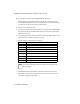
4. Locate the 8-position dip-switch on the main circuit board, approximately in the
center of the area exposed by the access opening.
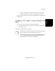
5. Set the positions of this dip-switch as follows:
6. If a ROM board was removed earlier, reinsert the board into its connector.
7. Replace the access panel by placing it into position and pressing down at the
rear edge to engage the locking tabs.
Position State
1ON
2 N/A (not connected)
3 N/A (not connected)
4 N/A (not connected)
5OFF
6OFF
7OFF
8OFF
Note
The position settings listed above for switches 2 through 8 are the
factory defaults.